Minitype composite vibration power generator

A vibration generator and compound technology, applied in the directions of generators/motors, electrical components, electromechanical devices, etc., can solve the problems of hindering development and application, reduce the natural frequency of the structure, small bearing capacity, etc., to expand the operating frequency range, The effect of improving stress conditions and reducing natural frequencies

Inactive Publication Date: 2011-09-14
NORTH CHINA ELECTRIC POWER UNIV (BAODING)
View PDF9 Cites 40 Cited by
  • Summary
  • Abstract
  • Description
  • Claims
  • Application Information

AI Technical Summary

Problems solved by technology

The generator is easy to integrate with other MEMS devices. However, the capacitor needs to be polarized under the action of an external electric field when it starts to work. To some extent, it is still limited by the working environment, which hinders its further development and application.
Chinese patents 200910080541.9 and 201010245136.6 invented the electromagnetic vibration generator, which overcomes the shortcomings of the capacitor generator that needs an external voltage to start working. However, due to its complex structure and the separation of the coil and the magnet, it is difficult to miniaturize
Chinese...

Method used


Image

  • Minitype composite vibration power generator
  • Minitype composite vibration power generator
  • Minitype composite vibration power generator

Examples


Embodiment 1

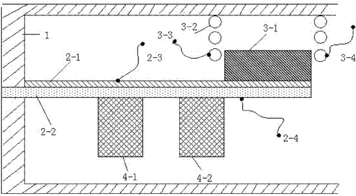
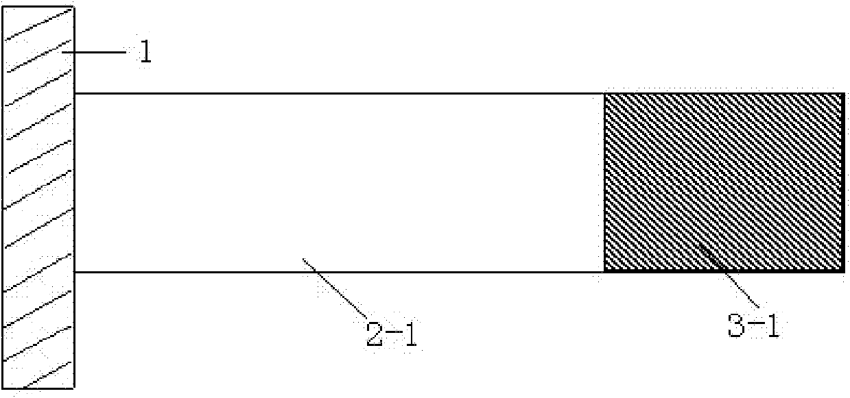
[0035] Such as figure 1 , 2 As shown, the miniature composite vibration generator includes the following parts: an insulating shell 1, a piezoelectric sheet 2-1, a supporting substrate 2-2, piezoelectric generating output wires 2-3, 2-4, a permanent magnet 3-1, Inductance coil 3-2, electromagnetic power generation output wires 3-3, 3-4, dispersed masses 4-1, 4-2, wherein the piezoelectric cantilever beam is composed of a piezoelectric sheet 2-1 and a supporting substrate 2-2, The material of the supporting substrate 2-2 is phosphor bronze, one end of the supporting substrate 2-2 is fixed on the insulating shell 1, the piezoelectric sheet 2-1 is made of PZT-5H material, the polarization direction is the same as the thickness direction, and pasted by conductive adhesive On the upper layer of the supporting substrate 2-2, the permanent magnet 3-1 is pasted on the upper layer of the end of the piezoelectric sheet 2-1, and the electromagnetic coil 3-2 directly above the permanent ...

Embodiment 2

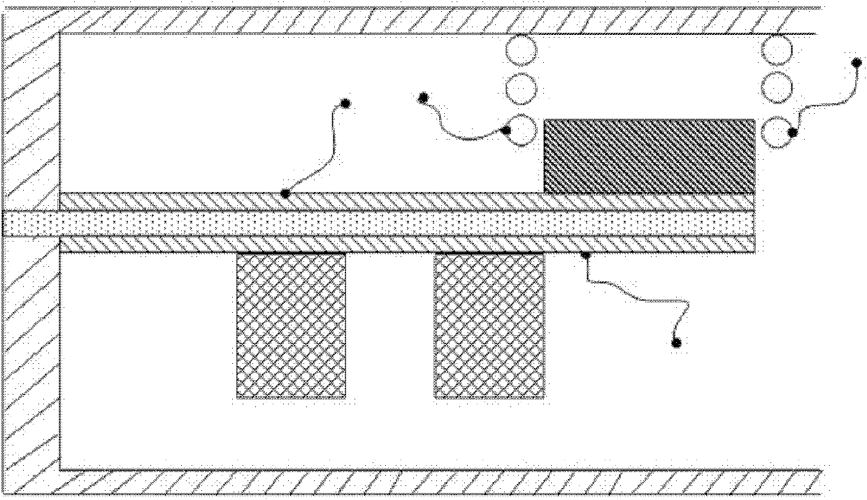
[0039] Such as image 3 As shown, the piezoelectric cantilever beam is composed of two piezoelectric sheets and a supporting substrate, and the piezoelectric sheets are pasted on the upper and lower surfaces of the supporting substrate respectively. Other conditions are identical with embodiment 1.

Embodiment 3

[0041] Such as Figure 4 As shown, there are two masses, which are pasted on the upper and lower surfaces of the piezoelectric cantilever respectively. Other conditions are identical with embodiment 2.


PUM


Abstract

The invention discloses a minitype composite vibration power generator belonging to the field of minitype power technology and energy-saving technology. The minitype composite vibration power generator is a cantilever beam vibration power generator compounded by piezoelectricity and electromagnetism and mainly comprises an insulating shell, a piezoelectric cantilever beam, a permanent magnet and an inductance coil, wherein the piezoelectric cantilever beam consists of a piezoelectric sheet and a supporting substrate; the piezoelectric sheet is bonded on the supporting substrate; one end of the supporting substrate is fixed on the insulating shell; the permanent magnet is bonded with a free end of the piezoelectric cantilever beam; and an inductance coil is arranged right above the permanent magnet. Under the resonant state, the power generator synchronously outputs the piezoelectric current and the electromagnetic current; the output power is improved within the finite volume; furthermore, by adopting the structure of dispersing mass blocks, the energy collecting density is improved, and the working frequency scope is enlarged simultaneously.

Description

technical field [0001] The invention belongs to the field of micro-power supply technology and energy-saving technology, and in particular relates to a micro-composite vibration generator. Background technique [0002] Wireless and portable miniature electronic products, because of their extremely low energy consumption, can be widely distributed in places with harsh environmental conditions and inaccessible to humans, or can be implanted inside the object to be measured, have promoted medical implantation, embedded Sensors, wireless sensor networks and other high-tech rapid development. However, the harsh working conditions of microelectronic products make it difficult for traditional power supply methods such as batteries and wired power supplies to meet their special requirements for power supplies. For example, various medical implants and structure-embedded microsensors require the system to be free from the shackles of the power cord; traditional batteries have shortc...

Claims


Application Information

Patent Timeline
IPC IPC(8): H02N2/18H02K35/02
Inventor 何青闫震杜冬梅
Owner NORTH CHINA ELECTRIC POWER UNIV (BAODING)
Why Eureka
Try Eureka