Production method for a paint plant component and corresponding paint plant component

A technology of spraying equipment and production method, which is applied in the production of components and the field of production of spraying equipment components, can solve the problems of no coating equipment component reference, etc., and achieve the effect of low weight

Inactive Publication Date: 2011-09-14
DUERR SYST GMBH
View PDF19 Cites 5 Cited by
  • Summary
  • Abstract
  • Description
  • Claims
  • Application Information

AI Technical Summary

Problems solved by technology

[0011] Documents WO 2004/073889 A1, DE 10 2007 009 277 A1, DE 10 2004 041 633 A1, DE 10 2004 012 682 A1, DE 601 14 453 T2, DE 600 14 714 T2, DE 10310 385 OS B4 and DE 1015 The company p

Method used


Image

  • Production method for a paint plant component and corresponding paint plant component
  • Production method for a paint plant component and corresponding paint plant component
  • Production method for a paint plant component and corresponding paint plant component

Examples


Embodiment Construction

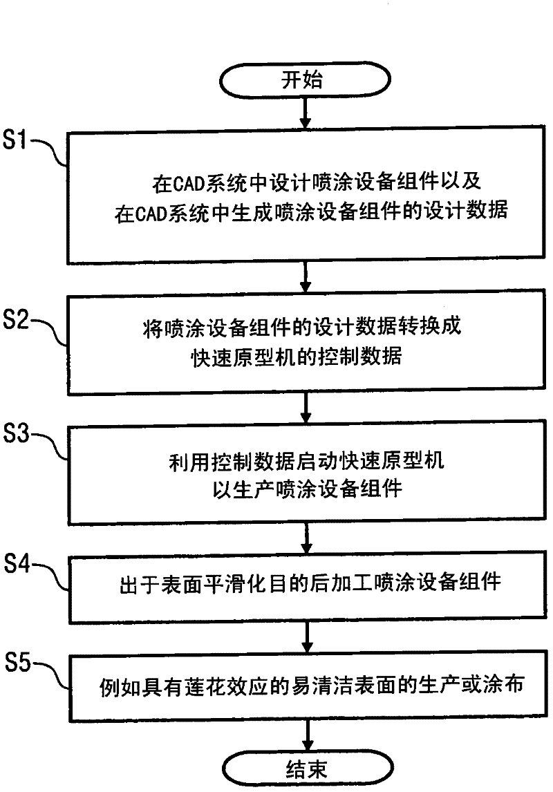
[0078] in such as figure 1 In the illustrated production method according to the invention, firstly, in a first step S1 , the spraying system component is designed in the conventional manner in a CAD system, in which design data for the spraying system component are generated. By way of example, the design data here can be in the known STL format (STL: Standard Triangulation Language), but other data formats are also possible in principle.

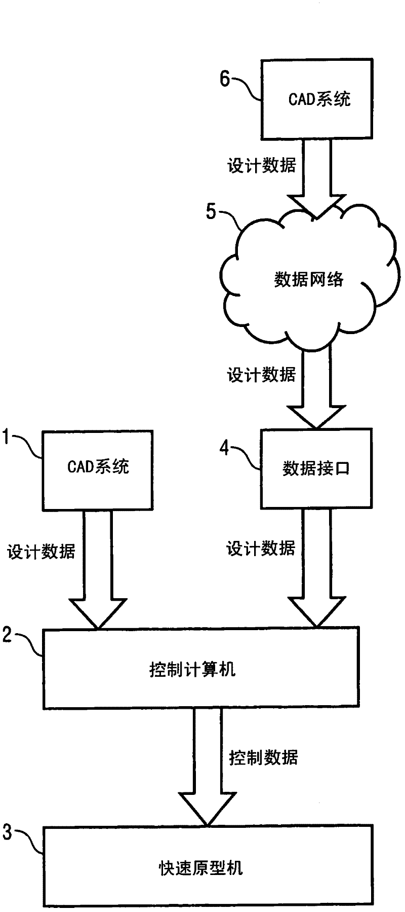
[0079] In the next step S2, the painting equipment component design data are then converted into control data for the rapid prototyping machine. The rapid prototyping machine may for example be a machine of the type EOSINT P390, P700 or P730 or FORMIGA P100 commercially available from EOS Corporation.

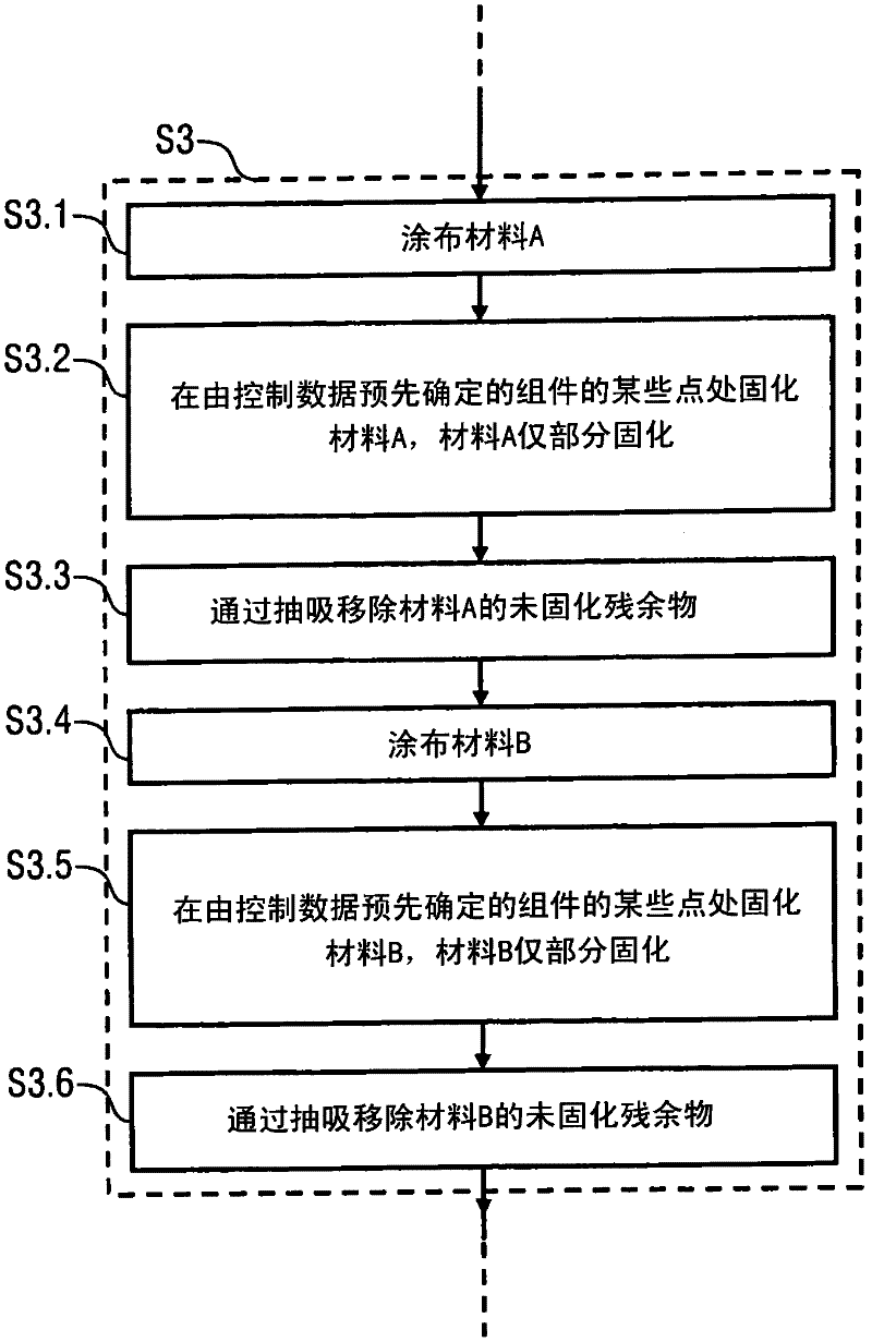
[0080] In a next step S3, the rapid prototyping machine is then started with the control data to produce the spraying equipment components.

[0081] Subsequent processing of the coating system components for the purpose of surface smoothi...


PUM


Abstract

The invention relates to a production method for producing a paint plant component, in particular for producing a component of a colour changer, a colour valve, or a spray device. According to the invention, the paint plant component is produced in a rapid prototyping method. The invention also relates to a paint plant component that is produced accordingly.

Description

technical field [0001] The invention relates to a production method for producing spraying (painting) equipment components, in particular to a production method for producing components such as a color changer, a color material valve, a sprayer, and a robot. The invention also relates to a correspondingly produced spraying system assembly. Background technique [0002] Painting equipment components used in motor vehicle painting equipment such as components of color changers, toner valves or sprayers are typically produced by material removal production methods (e.g. rolling, drilling) or basic forming methods (e.g. casting, extrusion) , because these production methods allow the necessary low surface roughness of spray equipment components. [0003] A disadvantage of these known production methods is the limited design freedom in shaping, since certain component shapes cannot be achieved using the corresponding production methods. For example, through-lines for media (e.g...

Claims


Application Information

Patent Timeline
IPC IPC(8): B29C67/00B05B13/00B05B15/50
CPCB05B3/1092B29C67/0085B29K2995/0073B05B15/02B05B12/149B05B15/50B33Y10/00B29C64/10B33Y80/00B29C64/30B29C64/188B33Y70/00B33Y30/00
Inventor S·韦塞尔基H-G·弗里茨F·赫勒T·贝尔
Owner DUERR SYST GMBH
Why Eureka
Try Eureka