
Biomass whirlwind hot blast stove
A hot blast stove, biomass technology, applied in air heaters, fluid heaters, lighting and heating equipment, etc., can solve the problems of large amount of smoke and dust, low thermal efficiency, insufficient combustion, etc., to save consumption and improve combustion efficiency , The effect of reducing dust content
- Summary
- Abstract
- Description
- Claims
- Application Information
AI Technical Summary
Problems solved by technology
Method used
Image

Examples
Embodiment Construction
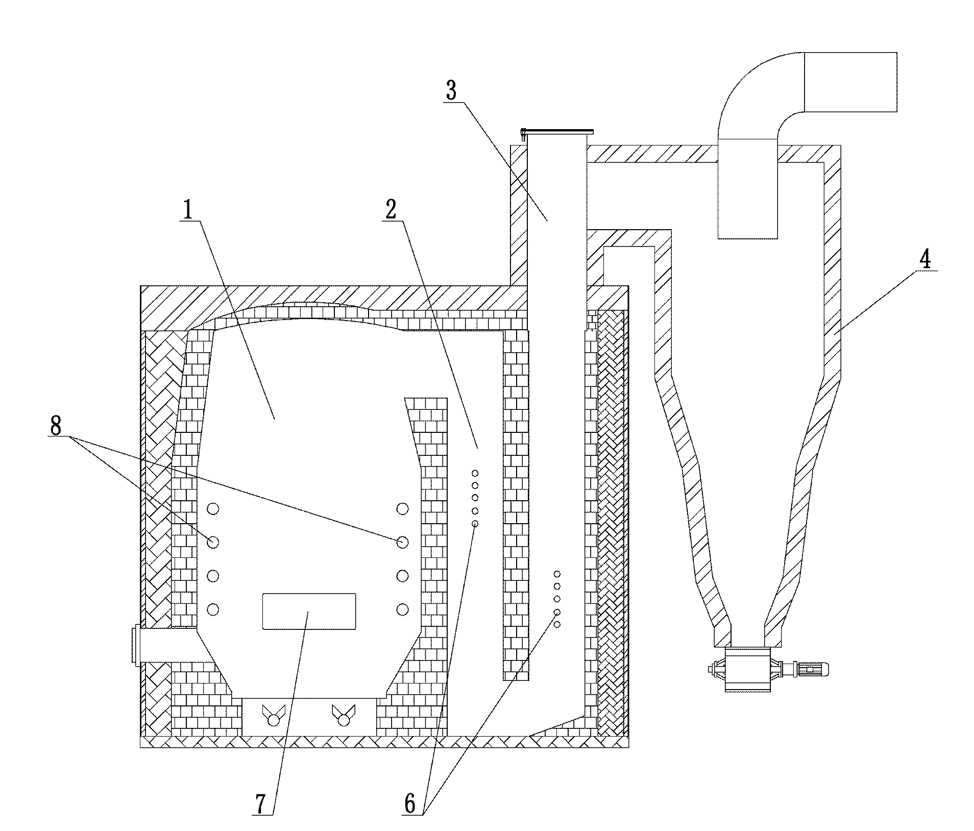
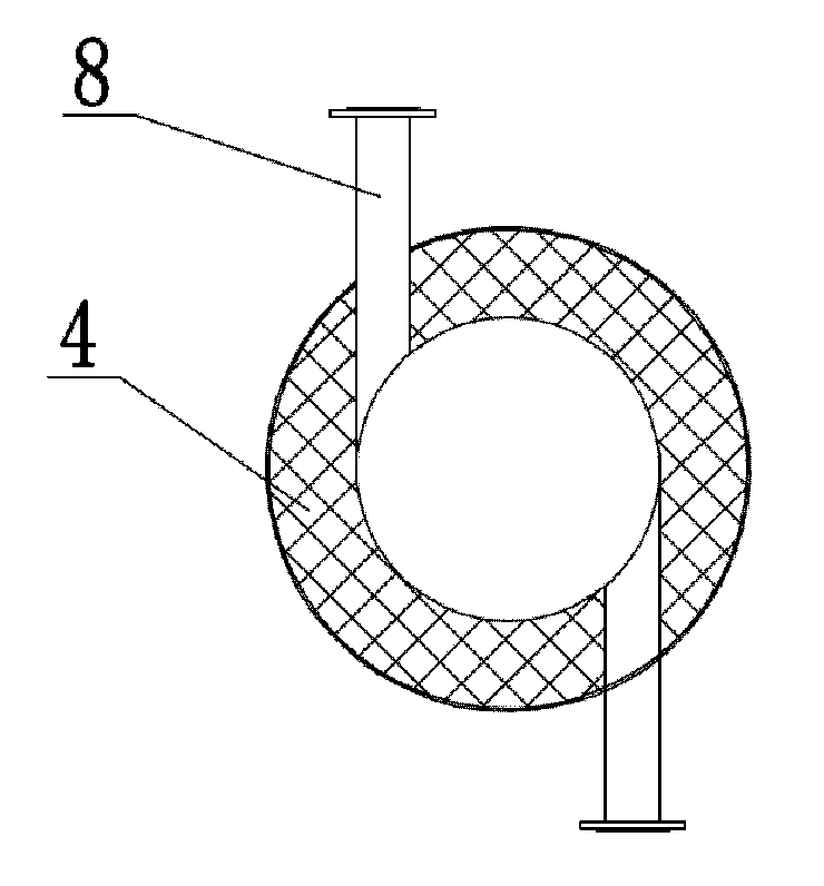
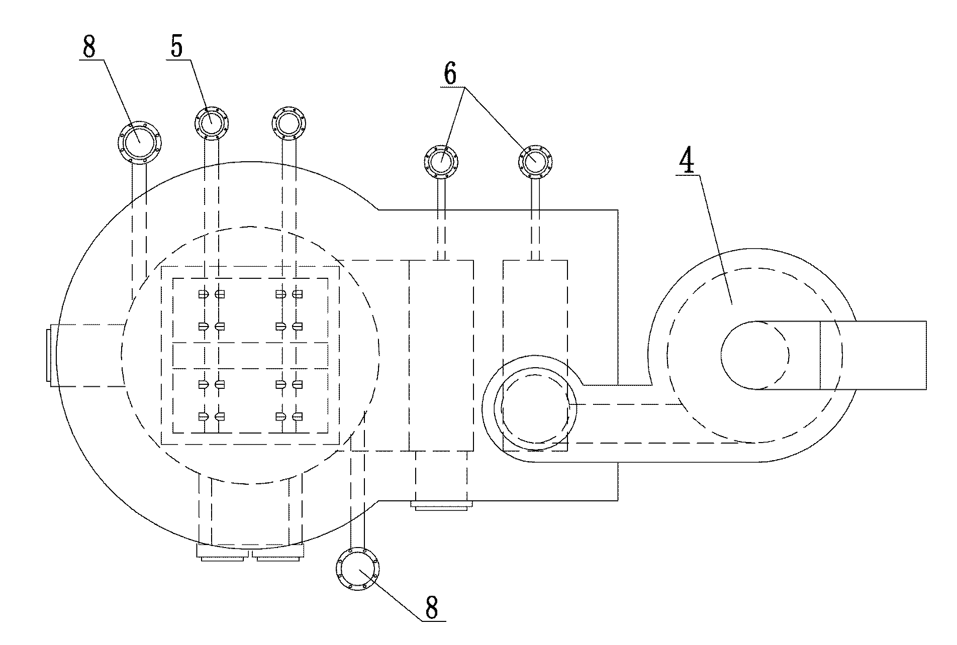
[0021] Such as figure 1 , figure 2 As shown, the hot blast stove of the present invention is improved from the original rectangular hot blast stove, and the combustion chamber of the hot blast stove is separated into three combustion chambers with different functions, so as to realize more effective segmented combustion. The hot blast stove of the present invention is made up of main combustion chamber 1, auxiliary combustion chamber 2, settling chamber 3 and cyclone dust collector 4. The inner cavity of the main combustion chamber 1 is a cylindrical structure, and the side wall of the main combustion chamber 1 is provided with some primary air holes 8, and the inwall of the primary air holes 8 is vertically tangent to the side wall of the main combustion chamber 1 ( image 3 ). The inner cavity of the secondary combustion chamber 1 and the settling chamber 3 is square (certainly also can be cylindrical), and the side walls of the secondary combustion chamber 2 and the sett...
PUM
 Abstract
Description
Claims
Application Information