
Gas drying system and method

A gas drying and drying technology, which is applied in the direction of separation methods, chemical instruments and methods, and other chemical processes, can solve the problems of easy retention, decreased drying efficiency of dryers, and waste of drying gas, etc., to achieve increased efficiency, convenient operation, easy to control effects

Inactive Publication Date: 2011-10-05
NAT INST OF METROLOGY CHINA
View PDF7 Cites 9 Cited by
  • Summary
  • Abstract
  • Description
  • Claims
  • Application Information

AI Technical Summary

Problems solved by technology

[0004] Most of the existing compressed air drying equipment is large-scale drying equipment used in factories, which has poor control over the dew point of the dry gas and cannot fully absorb the moisture in the air to achieve a stable outlet dew point; and the gas distribution in the tower is uneven, prone to entrapment
In addition, the double-tower dryers in the prior art often use too much drying gas when regenerating the adsorbent, resulting in a waste of drying gas and a decrease in the drying efficiency of the dryer.
[0005] In addition, the large-scale drying equipment used in the factory cannot be applied to occasions such as laboratories where dry gas is required in some local areas, causing the inconvenience of drying gas in small areas

Method used


Image

  • Gas drying system and method
  • Gas drying system and method
  • Gas drying system and method

Examples


Embodiment Construction

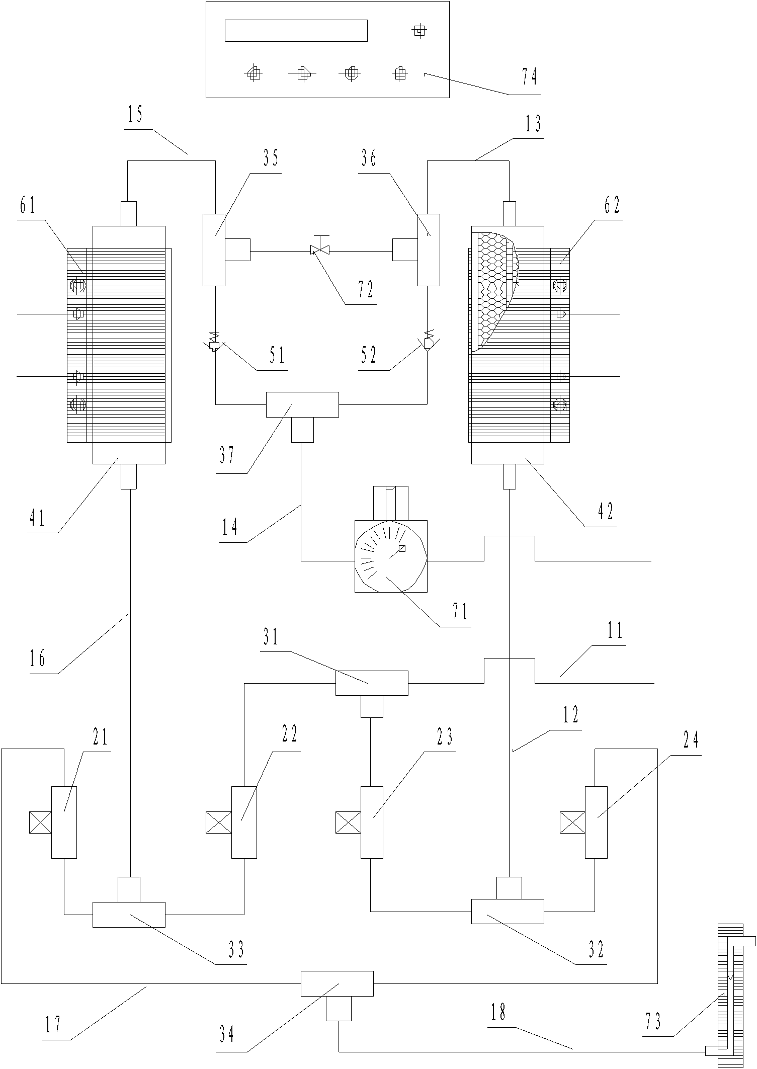
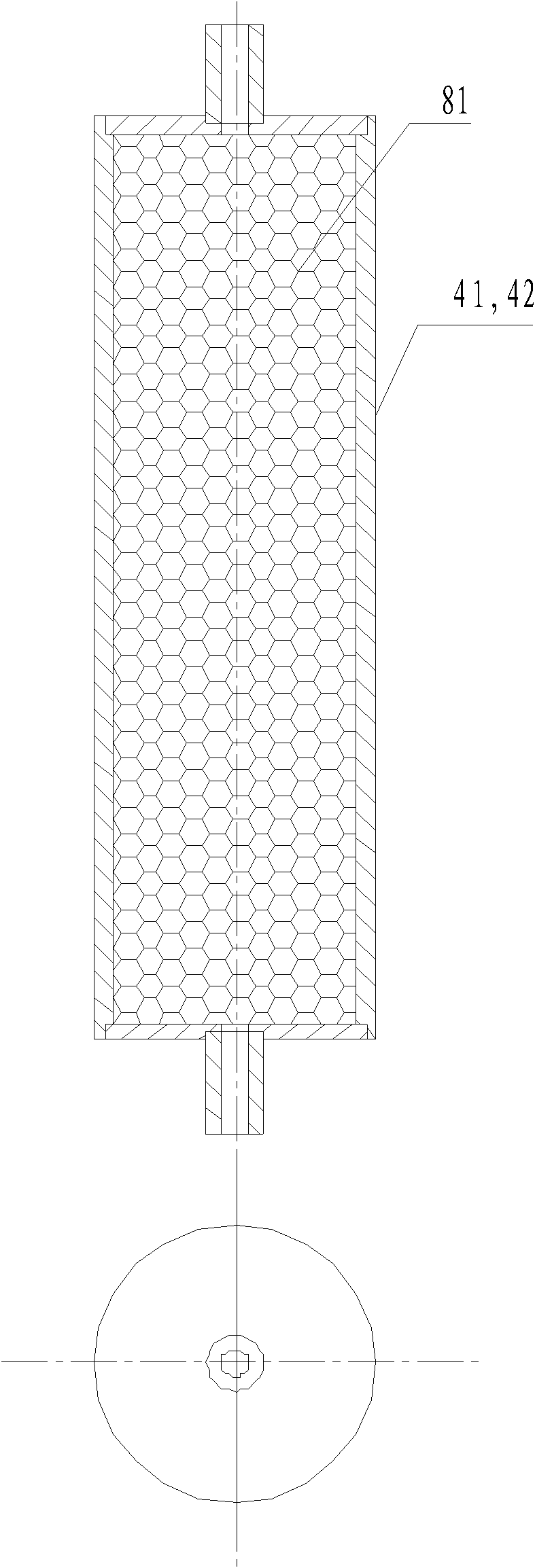
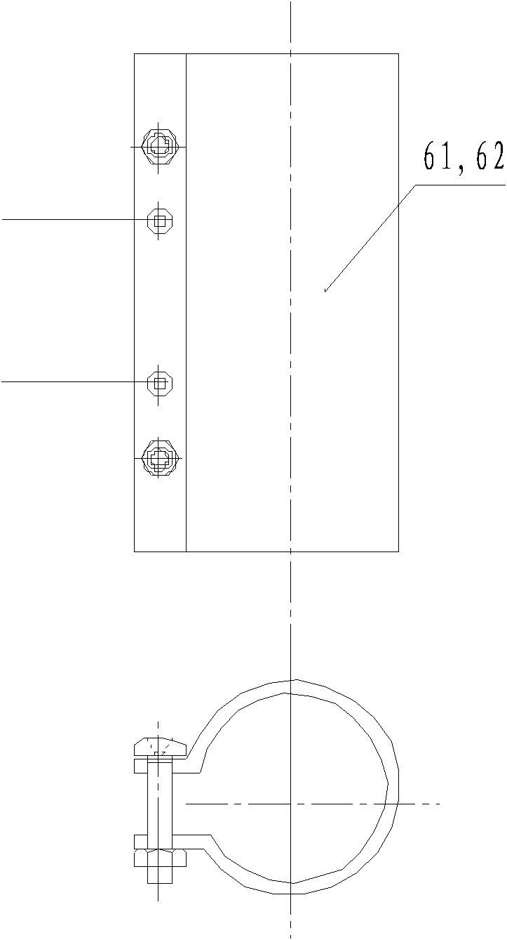
[0042] Specific embodiments of the present invention will be described in detail below in conjunction with the accompanying drawings.

[0043] The present invention adopts the method of combining the two principles of pressure swing adsorption and temperature swing adsorption, that is, the desorption efficiency of the moisture of the adsorbent is increased by the dry gas after heating, and the drying and drying of the gas are carried out in circulation between two dryers. Activation and regeneration of the adsorbent.

[0044] The gas drying system provided by the present invention includes two dryers (the first dryer and the second dryer), electromagnetic valves connected between the lower interface of the two dryers, the gas inlet and the moisture exhaust outlet respectively, The one-way check valve between the upper interface of the two dryers and the gas outlet is respectively connected with the solenoid valve to control the time controller for opening and closing of the el...


PUM


Abstract

The invention provides a gas drying system which comprises a first dryer, a second dryer, electromagnetic valves, a check valve, time controllers, a needle valve and a pressure regulator, wherein the electromagnetic valves are respectively connected between lower ports of the two dryers and a moisture discharging outlet and between gas inlets of the two dryers and the moisture discharging outlet;the check valve is connected between upper ports and gas outlets of the two dryers; the time controllers are respectively used for controlling the electromagnetic valves to open and close; the needlevalve is connected between the two dryers to regulate ratio of drying gases required for regenerating absorbing agents in the two dryers; and the pressure regulator is connected to the gas outlet ends of the two dryers to regulate the flow of the drying gases. Meanwhile, the time controllers are used for controlling the electromagnetic valves to open and close and the working time of a heater according to the dew-point temperature of dried gases; and heating sleeves are respectively arranged outside the two heaters so as to utilize a part of drying gases output from the other dryer to regenerate the absorbing agent in the heated dryer. The invention has the advantages of simple structure and high desorption efficiency, and can be convenient for controlling output flow of the drying gases.

Description

technical field [0001] The invention relates to the technical field of gas drying, and more specifically, to a heating type gas automatic regeneration drying method and system. Background technique [0002] In various automation industrial applications, compressed air is an air source with multiple uses. During the process of air compression, the water vapor contained in it is compressed together, resulting in a relatively high atmospheric dew point of the compressed air. Generally, the relative humidity in the atmosphere is as high as 65%, and the humid saturated air formed after compression and condensation will inevitably contain a large number of liquid water droplets, which are the root cause of corrosion of equipment, pipes and valves. [0003] Excessive moisture in compressed air, whether in the liquid or vapor phase, can cause various problems for user operations, such as damage to items such as electrical components in containers, and damage to materials in pipeline...

Claims


Application Information

Patent Timeline
Patent Type & Authority Applications(China)
IPC IPC(8): B01D53/26B01J20/30B01D53/047
Inventor 李佳孙国华王海峰盛灵慧
Owner NAT INST OF METROLOGY CHINA
Learn More