Rotational flow mixer

A technology of swirl mixer and swirl channel, which is applied in the direction of mixers, biochemical instruments, chemical instruments and methods, etc., can solve the problems of large jet tube resistance, short residence time, low air utilization rate, etc., and achieve the inlet air pressure Low temperature, large gas-liquid contact area, and high air utilization

Active Publication Date: 2011-10-12
陆飞浩
View PDF7 Cites 9 Cited by
  • Summary
  • Abstract
  • Description
  • Claims
  • Application Information

AI Technical Summary

Problems solved by technology

The straight-through type means that the air pipe is introduced from the center opening of the tank bottom, and the air is directly sprayed upwards, or introduced from the tank wall opening to the center of the tank bottom, the nozzle is downward, and the air bounces downward when meeting the bottom of the tank and then upwards. The air residence time is the shortest, and the air utilization rate is the lowest; in contrast, the distribution of small holes in the annular tube and the distribution of the annular jet tube are better. Connect an annular pipe, and there are many small holes distributed on the annular pipe, the air is ejected from these small holes, which increases the residence time of the air, increases the gas-liquid contact area, and improves the utilization rate of the air, but the small holes of the annular pipe It is difficult to determine the diameter of distributed small holes. Too small holes are easy to cause blockage. Too large holes have large bubble diameters, which do not help to increase the residence time; The ring pipe is connected with multiple injection pipes. Each injection pipe is at a certain angle and is evenly distributed around the central axis of the fermenter. The compressed air uses its own static pressure to transform into a high-speed jet, which attracts the fermentation liquid and mixes it into a gas-liquid mixture. phase emulsion
Therefore, an energy-saving fermentation tank named 00267163.8 appeared. The basic structure includes a tank body, a mechanical stirring device and a multi-stage jet mixing device. The multi-stage jet mixing device includes an air distributor connected to the compressed air inlet pipe at the bottom of the tank body. There are 3-8 air nozzles evenly distributed on the device, and a two-stage or multi-stage jet mixer is installed along the spray direction behind each nozzle, which has obtained a better effect of dissolved oxygen, but it still has many defects, such as gas Insufficient mixing with liquid, short gas residence time; high jet tube resistance, high air pressure is required, the outlet pressure and power consumption of the air compressor must be increased, otherwise the mixing effect is poor, so overall it is not energy-saving; multi-stage jet There are many connection nodes in the mixing device, which is easy to be contaminated with bacteria; and because the flow rate of the air nozzle on the distributor is very high, the shear damage to the cells of the fermentation production bacteria is large, which affects the cell growth, prolongs the production cycle, and affects the production efficiency

Method used


Image

  • Rotational flow mixer
  • Rotational flow mixer
  • Rotational flow mixer

Examples


Embodiment Construction

[0015] The present invention will be further described in detail below in conjunction with the accompanying drawings and embodiments.

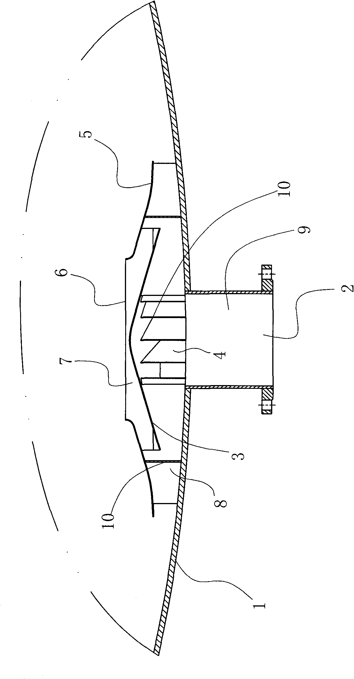
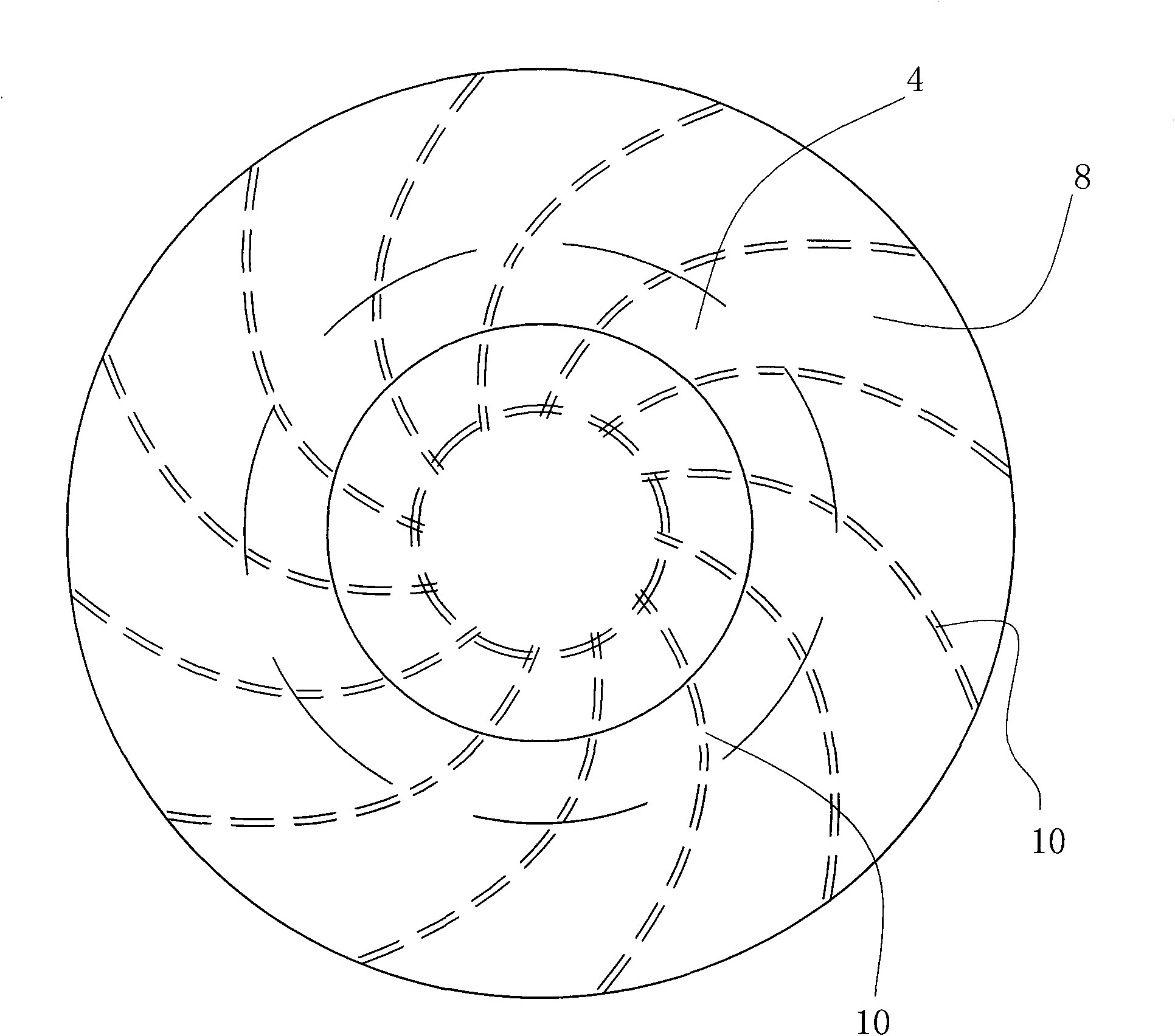
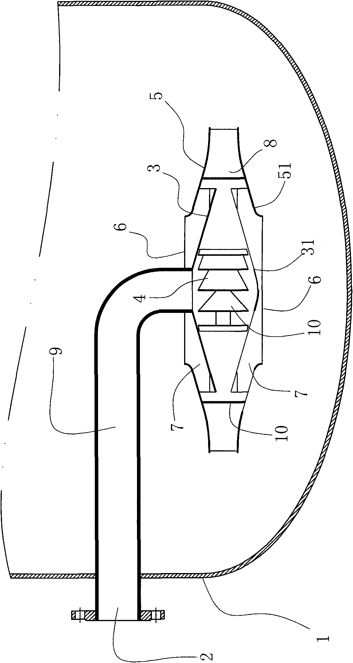
[0016] A cyclone mixer at least includes a container 1 for containing liquid, and an air inlet 2 is arranged on the container 1 .

[0017] Embodiment one of the present invention (as Figure 1~2 Shown): the air inlet 2 is arranged at the bottom center of the container 1, and an inner shell 3 similar to a conical cap shape is arranged above the air inlet 2, and an inner shell 3 is arranged between the inner shell 3 and the inner wall of the container 1. There is a gas phase swirl channel 4, and an outer shell 5 similar to an umbrella surface is arranged on the top of the inner shell 3. A liquid inlet 6 is opened in the middle of the outer shell 5, and a fluid swirl is formed between the outer shell 5 and the inner shell 3. The flow channel 7, the outer end of the gas phase swirl channel 4 and the fluid swirl channel 7 naturally merge into a ga...


PUM


Abstract

The invention relates to a rotational flow mixer, at least comprising a reaction container for filling liquid, wherein an air inlet is arranged on the container. The rotational flow mixer is characterized in that inner shells are arranged above the air inlet, a gas phase rotational flow passage is formed between the inner shells and the inner wall of the container or between the inner shells, outer shells are arranged above the inner shell, a liquid inlet is arranged in the middle of each outer shell, a fluid rotational flow passage is formed between the outer shells and the inner shells, theouter end parts of the gas phase rotational flow passage and the fluid rotational flow passage are converged into a gas-liquid mixed flow rotational flow passage, and the gas-liquid mixed flow rotational flow passage is located between the outer shells and the inner wall of the container or between the outer shells so that the gas-liquid mixed effect is favourable, a gas-liquid contact area is big, and the rotational flow mixer can be also used as a pneumatic stirrer.

Description

technical field [0001] The invention relates to an air intake device of a fermenter, in particular to a swirl mixer. Background technique [0002] Aerobic fermentation requires clean, dry, and bacteria-free air, which also requires a certain pressure to overcome the static pressure generated by equipment, pipeline resistance loss, and liquid submerged fermentation substrate. Since the solubility of compressed air in the fermentation broth is very low, it is passed from the bottom of the tank to the top of the tank, and the residence time is very short. Therefore, it is very meaningful to study various air intake devices to improve the efficiency of air utilization. [0003] There are three types of air intake devices at the bottom of the existing fermenter, which are straight-through type, distributed with small holes in annular tubes and distributed with annular jet tubes. The straight-through type means that the air pipe is introduced from the center opening of the tank b...

Claims


Application Information

Patent Timeline
Patent Type & Authority Applications(China)
IPC IPC(8): B01F13/02C12M1/107B01F33/40
CPCC12M27/20C12M27/02C12M29/06
Inventor 陆飞浩
Owner 陆飞浩
Why Eureka
Try Eureka