Front electrode structure of solar battery and manufacturing method of front electrode structure

A front electrode and solar cell technology, applied in the field of solar cells, can solve the problems of reducing the shading area of ​​the front electrode, high production cost, and reducing the shading area, so as to avoid the reduction of photoelectric conversion efficiency, improve the conversion efficiency, and reduce the effect of shading area

Inactive Publication Date: 2011-10-12
陕西众森电能科技有限公司
View PDF6 Cites 17 Cited by
  • Summary
  • Abstract
  • Description
  • Claims
  • Application Information

AI Technical Summary

Problems solved by technology

Among them, screen printing is currently the main electrode production method, but it is difficult to achieve a fine grid line of less than 100 microns in screen printing, and mainstream equipment can only achieve 120-150 microns, so that the shading area of ​​the front electrode reaches 5-8%. Restricting the further improvement of battery efficiency
[0003] Patent CN100576578C provides an electrode manufacturing method of electroless plating groove buried grid, the width of the thin grid line can be reduced to less than 50 microns, which greatly reduces the shading area of ​​the front electrode, but this method is difficult for industrial processing and the production cost high
[0004] Patent CN101483199A provides a new type of electrode structure, which uses conductive metal wires with a diameter of 0.1-0.17 mm as bus grid lines, cancels the main grid lines, reduces the shading area with a width of about 3 mm, and can improve the conversion efficiency of solar cells , but its production method is to print silver paste on the front of the battery using a conventional screen printing process to make uniformly distributed point electrodes, and then weld the metal wires on the points point by point, but this common process is complicated and time-consuming. increase the cost of industrialization

Method used


Image

  • Front electrode structure of solar battery and manufacturing method of front electrode structure
  • Front electrode structure of solar battery and manufacturing method of front electrode structure
  • Front electrode structure of solar battery and manufacturing method of front electrode structure

Examples


Embodiment 1

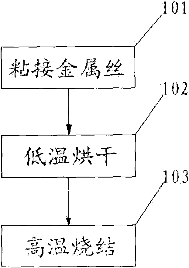
[0036] figure 1 It is a schematic flow chart of a method for manufacturing the front electrode of a solar cell according to the first embodiment of the present invention. See figure 1 As shown, the method mainly includes the following steps:

[0037] Step 101: bonding metal wires;

[0038] Paste the metal wire with silver paste on the surface of the silicon wafer to form thin grid lines;

[0039] Step 102: low temperature drying;

[0040] Dry the silicon wafers with metal wires at a temperature of 200°C to 400°C;

[0041] Step 101: high temperature sintering;

[0042] The dried silicon wafer is sintered at a temperature of 700°C to 900°C. At the same time, the silicon wafer and the back electrode are sintered together to form a good ohmic contact between the silver paste and the silicon wafer. The slurry and wire are sintered to form a complete conductor.

[0043] Ohmic contact refers to the contact between metal and semiconductor, and the resistance value of the contact surface is much...

Embodiment 2

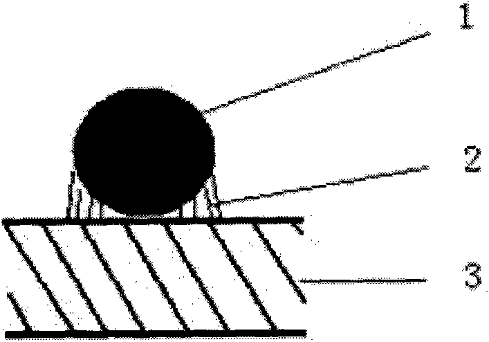
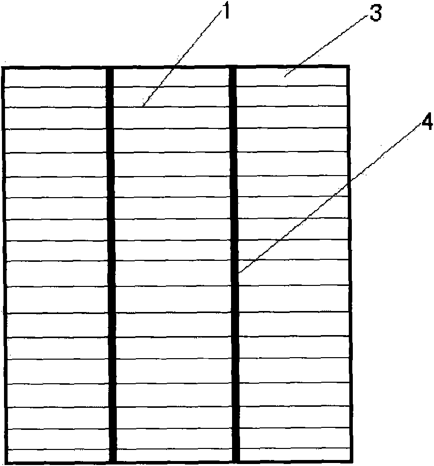
[0046] image 3 It is a schematic diagram of the structure of the front electrode of a solar cell according to the second embodiment of the present invention; figure 2 It is a partial cross-sectional schematic diagram of a front electrode structure of a solar cell of the present invention.

[0047] Such as figure 2 As shown, it includes a silicon wafer 3 and a metal wire 1. The silicon wafer 3 and the metal wire 1 are bonded together by a silver paste 2, and the metal wire 1 has a diameter of 0.01 mm to 0.15 mm.

[0048] Such as image 3 As shown, the metal wires 1 are bonded to the upper surface of the silicon wafer in parallel at equal intervals, and the distance between the metal wires is 1 to 3 mm.

[0049] Such as image 3 As shown, on the upper surface of the silicon wafer 3, there are provided main grid lines 4 in the direction perpendicular to the metal wire 1. There are two or three main grid lines 4, and the width of the main grid lines 4 is 1 to 3 mm. The spacing between...

Embodiment 3

[0053] Figure 4 It is a schematic diagram of the structure of the front electrode of a solar cell provided in the third embodiment of the present invention; figure 2 It is a partial cross-sectional schematic diagram of a front electrode structure of a solar cell of the present invention.

[0054] Such as figure 2 As shown, it includes a silicon wafer 3 and a metal wire 1. The silicon wafer 3 and the metal wire 1 are bonded together by a silver paste 2, and the metal wire 1 has a diameter of 0.01 mm to 0.15 mm.

[0055] Such as Figure 4 As shown, the metal wires 1 are bonded to the upper surface of the silicon wafer in parallel at equal intervals, and the distance between the metal wires is 1 to 3 mm.

[0056] Such as Figure 4 As shown, one end of the metal wire 1 is provided with an electrode lead-out section 5, and the electrode lead-out section 5 extends out of the upper surface of the silicon wafer 3 to lead out the front electrode.

[0057] In the production of this embodiment...


PUM

PropertyMeasurementUnit
widthaaaaaaaaaa
diameteraaaaaaaaaa

Abstract

The invention relates to the field of solar batteries, in particular to a front electrode structure of a solar battery and a manufacturing method of the front electrode structure. The manufacturing method comprises the following steps of: bonding, namely pasting silver paste on a metal wire and bonding the metal wire with the silver paste on the surface of a silicon slice so as to form a thin grid wire; drying, namely drying the silicon slice bonded with the metal wire at the temperature of 200 to 400 DEG C; and sintering, namely sintering the dried silicon slice at the temperature of 700 to 900 DEG C, so that high ohm contact is formed between the silver paste and the silicon slice, and the silver paste and the metal wire are sintered into a complete conductor. The structure comprises the silicon slice and the metal wire which are bonded with each other through the silver paste. In the invention, the metal wire is used for replacing the thin grid wire on the original silicon slice, so the thin grid wire is narrowed; therefore, the light shield area of the thin grid wire is reduced greatly and the conversion efficiency of the solar battery is improved.

Description

Technical field [0001] The invention relates to the field of solar cells, in particular to a front electrode structure of a solar cell and a manufacturing method thereof. Background technique [0002] Crystalline silicon solar cells are currently the mainstream solar cells. The production process is in sequence: de-damage layer texturing, diffusion, dephosphorization silicon glass, etching the periphery, PECVD deposition of silicon nitride passivation anti-reflection film, screen printing front and back The electrodes, the front and back electrodes are co-sintered. Among them, screen printing is the main electrode production method at present, but it is difficult for screen printing fine grid lines to be below 100 microns, and mainstream equipment can only achieve 120-150 microns, so the shading area of ​​the front electrode can reach 5-8%. It restricts the further improvement of battery efficiency. [0003] Patent CN100576578C provides a method for producing electrodes for chemi...

Claims


Application Information

Patent Timeline
Patent Type & Authority Applications(China)
IPC IPC(8): H01L31/18H01L31/0224
CPCY02P70/50
Inventor 黄国保
Owner 陕西众森电能科技有限公司
Why Eureka
Try Eureka