Annular capacitor with power conversion components

A capacitor and film capacitor technology, applied in the direction of tubular capacitors, wound capacitors, fixed capacitor terminals, etc., can solve the problem of voltage increase at the switch, reduce voltage overshoot, increase long-term reliability, and reduce effective series inductance. Effect

Inactive Publication Date: 2011-10-12
SBE
View PDF2 Cites 4 Cited by
  • Summary
  • Abstract
  • Description
  • Claims
  • Application Information

AI Technical Summary

Problems solved by technology

[0007] 3) The lower inductance of this capacitor to the switch reduces the voltage rise at the switch during switch off

Method used


Image

  • Annular capacitor with power conversion components
  • Annular capacitor with power conversion components
  • Annular capacitor with power conversion components

Examples


Embodiment Construction

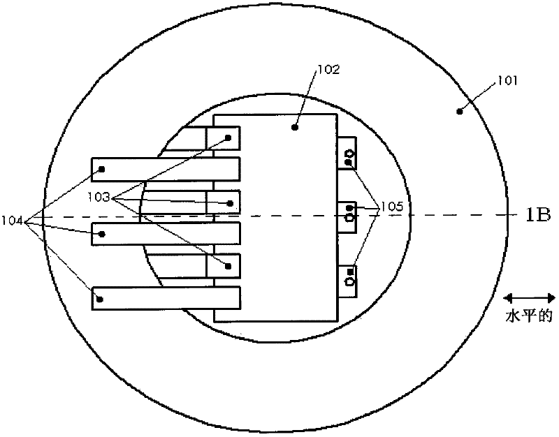
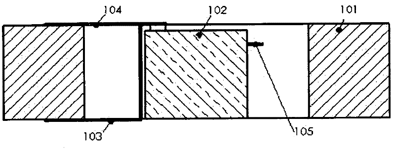
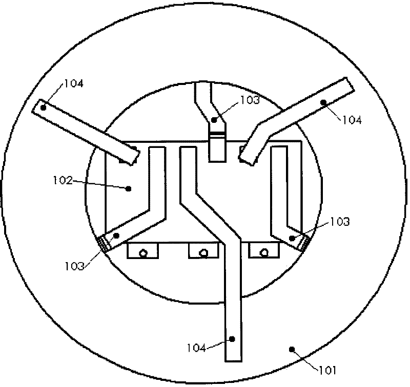
[0034] exist figure 1 A metallized film polymer ring capacitor with a single power conversion component is shown in . The annular capacitor body 101 has a variable center hole radius, allowing the power conversion component 102 to be tailored to specific specifications, leaving the necessary space for the component's upper terminal 104 , lower terminal 103 and output terminal 105 . exist figure 1 In , the terminals are positioned for the shortest possible path using typical commercially available power conversion components. The outer diameter and thickness of the ring capacitor can then be selected to achieve the desired capacitance for the power conversion application. exist Figure 1BThe thickness of the ring capacitor is indicated in (address). The depth of the ring capacitor 101 is made to match the height of the power conversion component 102 so that the terminals 103 and 104 can maintain the shortest distance for connection to the capacitor and thus the lowest con...


PUM


Abstract

The formation of an assembled unit consisting of an annular capacitor [a wound, metallized dielectric capacitor in the shape of a closed path ring] with other power conversion components arranged and attached in manners uniquely allowed by the ring design will allow higher density converter designs [power/unit volume]. The resulting short connection paths between the capacitor element and the switching semiconductors also provide a very low inductance path that minimizes voltage spikes on the switching semiconductors as a result of turn-off di/dt. The capacitor serves as a short time current source and sink for the switching semiconductors. With the described configuration the RMS current seen by the capacitor can be made more volumetrically uniform enabling more uniform capacitor rise. The single capacitor configured as described also mitigates bus resonance problems often observed in prior art when multiple discrete capacitors are connected in parallel.

Description

[0001] Related Application Cross Reference [0002] This application claims priority to U.S. Provisional Patent Application Nos. 60984561, 60984546, and 60984530, filed November 1, 2007, each entitled "Annual capacitor with semiconductors around the perimeter to perform power conversion", "Annual capacitor with semiconductor die or modules inside the hole for power conversion", and "Annual capacitor with power conversion semiconductor electronics contained inside the center hole", the subject matter of which are incorporated herein by reference. Here, the present invention is based on a recent patent 7,289,311 "Power ring pulse capacitor" issued on October 30, 2007 by the same inventor. technical field [0003] The present invention relates to ring factor capacitors for use as DC link capacitors in power conversion electronics. In particular, the invention relates to the selection of configurations for placing power switching devices around or within said capacitors which, fo...

Claims


Application Information

Patent Timeline
IPC IPC(8): H01G4/32
CPCH01G4/14H01G4/28H01G4/32H02M7/003Y10T29/53H05K7/14329H01G4/228
Inventor 特里·霍斯金
Owner SBE
Why Eureka
Try Eureka