Rapid forming working platform

A workbench and rapid technology, applied in the field of rapid prototyping workbench, can solve the problems of complex forming process of rapid prototyping equipment, difficult to observe, unable to handle in time, etc.

Active Publication Date: 2011-10-19
WUXI TIERTIME TECH CO LTD
View PDF6 Cites 2 Cited by
  • Summary
  • Abstract
  • Description
  • Claims
  • Application Information

AI Technical Summary

Problems solved by technology

[0005] In order to prevent the cooling speed of the forming material from being too fast, the rapid prototyping equipment in the prior art needs to add a forming chamber to provide the ambient temperature, which makes the rapid prototyping equipment complex and the forming process difficult to observe and thus cannot be processed in time. The defect of this kind of problem, the present invention provides a kind of rapid prototyping workbench, and this workbench is a kind of open workbench of self-heating, and this workbench itself has heating device in order to guarantee the environment temperature of forming material; Adopt this workbench There is no need to set up a forming room, so that the working process of material forming is fully visible so as to deal with various problems in real time in time

Method used


Image

  • Rapid forming working platform
  • Rapid forming working platform
  • Rapid forming working platform

Examples


Embodiment 1

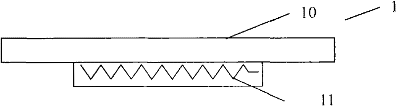
[0037] refer to figure 1, is a structural schematic diagram of the first embodiment of the rapid prototyping workbench of the present invention. The rapid prototyping workbench 1 includes a metal platform 10 and a heating device 11 sequentially from top to bottom, wherein the metal platform 10 can be an aluminum platform, a copper platform, an iron platform, etc., and the heating device 11 can be a resistance wire heating, a heating tube or Heating rod heating and other commonly used heating devices. During the forming process, the thermoplastic filament extruded from the nozzle solidifies and accumulates on the upper surface of the metal platform 10, that is, the support surface. During the extrusion and solidification process, the temperature of the thermoplastic filament is only cooled from the melting temperature to the softening temperature of the plastic. Warping deformation caused by excessive cooling of plastic is avoided. The softening temperature is provided by the...

Embodiment 2

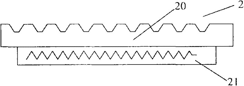
[0039] See figure 2 , is a schematic structural view of the second embodiment of the rapid prototyping workbench of the present invention. The rapid prototyping workbench 2 includes a glass platform 20 and a heating device 21 sequentially from top to bottom, grooves are evenly distributed on the upper surface (i.e. the support surface) of the glass platform 20 of the rapid prototyping workbench 2, the purpose is: its 1. Use a convex-concave surface instead of a smooth plane to increase the bonding area between the support surface and the bottom surface of the formed part, and improve the support force of the support surface to the formed part; 2. The thermal conductivity of glass is worse than that of metal materials. Opening grooves on the glass platform can partially reduce the thickness of the glass platform, which is more conducive to heat conduction. Of course, it is not limited to the form of opening grooves, and the concave holes or grid structures and other convex-co...

Embodiment 3

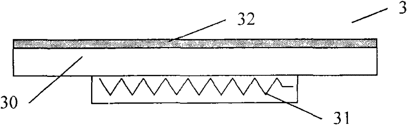
[0041] See image 3 , is a structural schematic diagram of the third embodiment of the rapid prototyping workbench of the present invention. Same as the rapid prototyping workbench 1 in embodiment 1, the rapid prototyping workbench 3 in this embodiment includes a metal platform 30 and a heating device 31 in order from top to bottom, but it is different from the rapid prototyping workbench 1 in embodiment 1 The difference is: the upper surface (i.e. the support surface) of the metal platform 30 of the rapid prototyping workbench 3 is coated with a polymer material layer, preferably a plastic layer 32, in order to increase the supporting force of the forming material during the forming process, Because the support surface of the metal platform 30 does not have enough bonding strength to the cured plastic forming part, it will easily cause the plastic forming part to shift on the metal support surface, which will affect the forming of the part. After the plastic layer 32 is coate...


PUM

PropertyMeasurementUnit
thicknessaaaaaaaaaa
thicknessaaaaaaaaaa

Abstract

Rapid forming equipment in the prior art needs to be additionally provided with a forming chamber so as to provide an environmental temperature for preventing over-fast temperature reduction speed of forming materials; therefore causing the defects of complex rapid forming equipment and hardly observed forming process as well as various problems generated in real time due to unable timely processing caused by the defects of complex rapid forming equipment and hardly observed forming process. The invention provides a rapid forming working platform, which comprises a support device and a heating device. The upper surface of the support device comprises a support surface used for supporting a forming piece; the heating device is used for heating the support device so as to improve an environmental temperature for squeezed forming materials. The working platform is a self-heated open type working platform and is provided with the heating device for guaranteeing the environmental temperature of the forming materials. When the working platform is adopted, a forming chamber is not needed; therefore, the material forming process is completely visible so that various problems generated in real time can be timely processed.

Description

technical field [0001] The invention belongs to the technical field of rapid prototyping, in particular to a rapid prototyping workbench. Background technique [0002] As an advanced manufacturing technology, rapid prototyping technology breaks the traditional manufacturing mode, uses the principle of discrete / stacking, without any tools and molds, and is directly driven by the CAD model to quickly complete parts of any complex shape, thus realizing from the product Digitization and automation from design to product manufacturing. [0003] Melted extrusion rapid prototyping (MEM~Melted Extrusion Modeling) technology is based on the geometric information determined by the computer based on the CAD model, controls the nozzle, melts the forming material into a molten state through the extrusion head of the heater, and makes the molten thermoplastic filament pass through the nozzle Extrusion, the extrusion head moves accurately along the contour of each section of the part, and...

Claims


Application Information

Patent Timeline
Patent Type & Authority Applications(China)
IPC IPC(8): B29C47/08B29C47/88B29C48/12B29C48/08
CPCB29C48/08B29C48/12
Inventor 郭戈唐果林颜旭涛
Owner WUXI TIERTIME TECH CO LTD
Why Eureka
Try Eureka