Real-time monitoring device for online writing weak optical fiber Bragg grating and application method thereof

A technology of weak fiber Bragg grating and monitoring device, which is applied in the coupling of optical waveguide, testing optical performance, etc., can solve the problems of difficult to ensure the strength and integrity of fiber Bragg grating, online monitoring of weak fiber Bragg grating, fiber damage, etc., and achieve shortening of fiber positioning Clamping time, convenient replacement, fast and convenient fiber optic docking effect

Active Publication Date: 2012-07-25
武汉烽理光电技术有限公司
View PDF0 Cites 0 Cited by
  • Summary
  • Abstract
  • Description
  • Claims
  • Application Information

AI Technical Summary

Problems solved by technology

One is that the UV-absorbing optical fiber polymer coating must be stripped during the conventional fiber grating manufacturing process, which will cause additional damage to the optical fiber and make it difficult to ensure the strength and integrity of the optical fiber grating
The second is that the above three methods are difficult to produce a large number of fiber gratings on the same optical fiber in a short period of time.
Therefore, how to export the signal and online monitor the writing status of the weak fiber grating has become a technical bottleneck

Method used


Image

  • Real-time monitoring device for online writing weak optical fiber Bragg grating and application method thereof
  • Real-time monitoring device for online writing weak optical fiber Bragg grating and application method thereof
  • Real-time monitoring device for online writing weak optical fiber Bragg grating and application method thereof

Examples


Embodiment

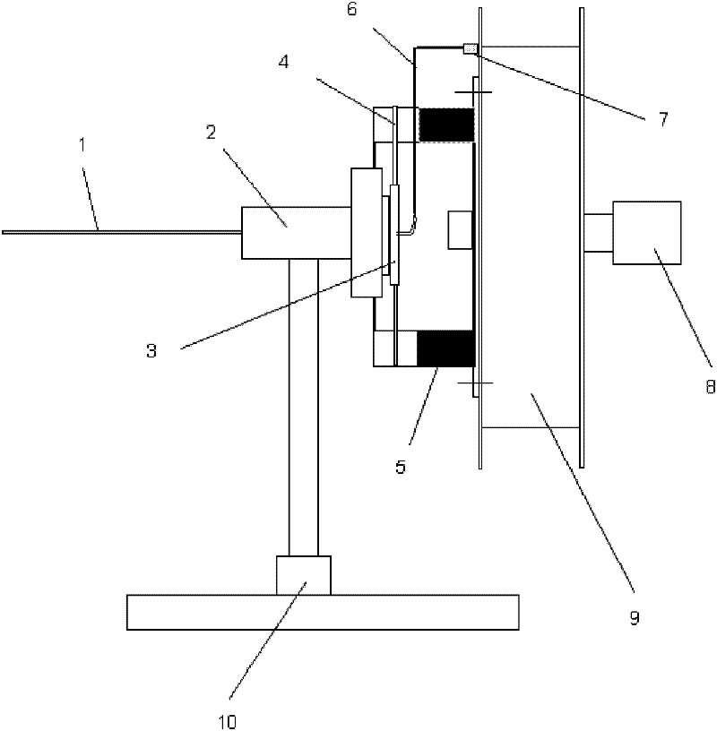
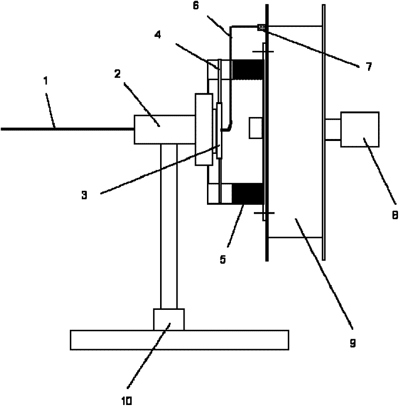
[0026] Such as figure 1 As shown, on the whole, the patent of the present invention mainly includes two parts: the quick combination and separation mechanism of the lever and the dial and the quick positioning clamper for the optical fiber. The technical scheme of the present invention will be described in detail below in conjunction with the accompanying drawings.

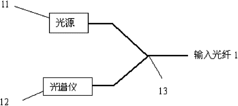
[0027] An on-line monitoring device for weak fiber grating writing status in the fiber drawing process of the present invention, the device includes an input optical fiber 1, a stator 2, a rotor 3, a lever 4, a cylinder 5, an output optical fiber 6, and a V-groove quick connection 7, motor 8, take-up reel 9, sliding guide rail 10, light source 11, spectrometer 12 and Y-shaped splitter 13; stator 2 is supported on sliding guide rail 10, one end of stator 2 is connected to input optical fiber 1, and rotor 3 is connected to output optical fiber 6 are connected, the stator 2 and the rotor 3 are non-contact coupling l...


PUM


Abstract

The invention provides a real-time monitoring device for online writing weak optical fiber Bragg grating and an application method thereof. The real-time monitoring device comprises an input optical fiber, a stator, a rotor, shift levers, a shift cylinder, an output optical fiber, a V-shaped slot quick connector, a motor, a take-up reel, a slideway, a light source, a spectrometer and a Y-shaped splitter, wherein the stator is supported on the slideway; one end of the stator is connected with the input optical fiber; the rotor is connected with the output optical fiber; the stator and the rotor can transmit light by a noncontact coupling way; the two shift levers are symmetrically arranged on the rotor up and down; two strip-shaped slots are symmetrically arranged on the shift cylinder up and down; the shift levers can pass in and out of the strip-shaped slots of the shift cylinder; the shift cylinder is fixed on the take-up reel that is fixed on a motor shaft; the V-shaped slot quick connector is fixed at the edge of the take-up reel; the output optical fiber passes through the strip-shaped slots of the shift cylinder, is butt-jointed and positioned with an optical fiber, on the take-up reel, in the V-shaped slot quick connector and then is clamped; one end of the Y-shaped splitter is connected with the light source and the spectrometer respectively; and the other end of the Y-shaped splitter is connected with the input optical fiber 1. The device is used for online monitoring of a write-in state of the weak optical fiber Bragg grating.

Description

technical field [0001] The invention relates to a real-time monitoring device for writing weak optical fiber gratings online and an application method thereof. The invention is mainly used for real-time on-line monitoring of the writing condition of weak gratings during the drawing process of optical fibers, and belongs to the technical field of optical fiber connections and sensors. technical background [0002] The weak fiber grating can be used as a filter to filter the noise of the amplified self-emitting optical amplifier before the signal is processed, and it is better than the F-P filter in improving the signal-to-noise ratio of the output signal. This filter has almost no intersymbol interference, and does not have a long fading tail like the pulse from the F-P transmissive filter, which avoids the occurrence of false detection. [0003] Another important application of weak fiber gratings is in the health monitoring of composite materials. Modern design is moving ...

Claims


Application Information

Patent Timeline
Patent Type & Authority Patents(China)
IPC IPC(8): G01M11/02G02B6/38
Inventor 姜德生李小甫余海湖郭会勇何伟文泓桥许儒泉
Owner 武汉烽理光电技术有限公司
Why Eureka
Try Eureka