Central shaft cutting-off mechanism for eight-shaft spring forming machine

A technology of cutting mechanism and shaft spring, which is applied in the direction of manufacturing springs, other household appliances, household appliances, etc. from wires, can solve the problems of not achieving the ideal technical effect, the mandrel is slightly moved, and the spring is prone to tail hooks, etc., so as to improve the product quality. The effect of quality and production efficiency, improving work efficiency, improving performance and reliability

Inactive Publication Date: 2013-04-10
盐城海旭数控装备有限公司
View PDF5 Cites 0 Cited by
  • Summary
  • Abstract
  • Description
  • Claims
  • Application Information

AI Technical Summary

Problems solved by technology

Among them, the mandrel mechanism and the cutting mechanism play an important role in the process of forming the spring. The steel wire is wound on the mandrel to form a spring shape. When the cutter cuts the steel wire, the mandrel plays a supporting role, and the large outer diameter spring When cutting, the cutting force is large, the mandrel will move slightly, and the processed spring is prone to tail hooks, so: the ideal technical effect cannot be achieved
In the same industry in China: scientific research units and enterprise scientific and technological personnel are constantly researching, exploring, and improving the structure of the shaft mechanism and cutting mechanism of the spring forming machine. Although some progress has been made in technology, there are still problems that have not been overcome in practical application. Due to the technical difficulties, we hope to develop a more accurate and complete spring forming machine shaft mechanism and cutting mechanism

Method used


Image

  • Central shaft cutting-off mechanism for eight-shaft spring forming machine
  • Central shaft cutting-off mechanism for eight-shaft spring forming machine

Examples


Embodiment Construction

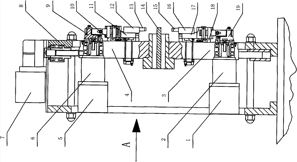
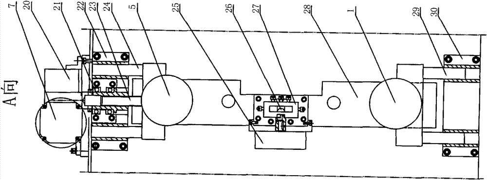
[0011] exist figure 1 , figure 2 Middle: The front wall panel 8 and the rear wall panel are connected with long bolts to form a rectangular support body, a servo motor 7 is arranged on the upper end of the support body, the servo motor 7 is connected with the reduction box 20, and the front wall panel 8 is provided with a rectangular support body. Groove, the core block 28 is arranged in the groove, fixed by the lifting nut 21, the core block 28 is in a rectangular shape, the lifting shaft 23 connects the reduction box 20 and the core block 28, and the upper guide sleeve seat 22 is respectively provided on both sides of the lifting shaft 23 , the upper guide column 24 is installed in the upper guide sleeve 22, the bottom end of the support body is provided with two lower guide sleeves 30, the lower guide sleeve 30 is respectively provided with a lower guide column 29, and the middle part of the core block 28 is provided with a rectangular hole, the rear of the rectangular ho...


PUM


Abstract

The invention discloses a central shaft cutting-off mechanism for an eight-shaft spring forming machine, which belongs to spring machining mechanical equipment. The mechanism is formed by combining a computer closed loop technology with a central shaft and cutting-off integrated design; all machining processes of a central shaft mechanism and a cutting-off mechanism of the spring forming machine are controlled by computer programs; parameters corresponding to springs of different models are set in a computer; and when a spring of a certain size is required to be machined, intelligent operation and data control can be realized only by inputting a corresponding parameter. The mechanism improves the performance and the reliability of a machine, has high sensitivity, quick response and high dimensional accuracy, reduces manual operation capacity, improves working efficiency, is safely and conveniently operated, and reduces energy source consumption. In the mechanism, central shaft and cutting-off integration is realized, so that a spring steel wire is not provided with a tail hook after being cut off; therefore, the mechanism has high product machining accuracy, and improves product quality and production efficiency.

Description

technical field [0001] The invention relates to a spring processing mechanical equipment, in particular to an eight-axis spring forming machine shaft cutting mechanism. Background technique [0002] In industries such as machinery, automobiles, tractors, and electrical appliances, springs, as one of the most basic mechanical parts, especially coil springs used for balance mechanisms in machinery, are widely used in various fields of national economy and social life. Therefore: Higher technical requirements are put forward for the mechanical equipment for processing springs. In the past, most of the equipment for processing springs was a purely mechanical spring coiling machine, with complex structure, single function, cumbersome debugging, and low processing accuracy. In order to improve production efficiency, many factories used single-chip microcomputers to control the forming of springs. At present, in the domestic market, the forming machine for coiling spiral compressi...

Claims


Application Information

Patent Timeline
Patent Type & Authority Patents(China)
IPC IPC(8): B21F35/00B21F11/00
Inventor 徐文锦陈新
Owner 盐城海旭数控装备有限公司
Why Eureka
Try Eureka