MDOF (multiple-degree-of-freedom) magnetic suspension motor

A magnetic levitation and degree of freedom technology, applied in the direction of electrical components, magnetic attraction or thrust holding devices, etc., can solve the problems that the transmission mechanism affects the positioning accuracy of the manipulator, destroys the stability of the system, and the manipulator is large in size, and achieves light weight, The effect of simple structure and small volume

Active Publication Date: 2011-11-09
HARBIN INST OF TECH
View PDF3 Cites 34 Cited by
  • Summary
  • Abstract
  • Description
  • Claims
  • Application Information

AI Technical Summary

Problems solved by technology

This not only causes the manipulator to be bulky, heavy, and has poor dynamic performance, but also the gap error of the transmission mechanism will directly affect the positioning accuracy of the manipulator, and even destroy the stability of the system.

Method used


Image

  • MDOF (multiple-degree-of-freedom) magnetic suspension motor
  • MDOF (multiple-degree-of-freedom) magnetic suspension motor
  • MDOF (multiple-degree-of-freedom) magnetic suspension motor

Examples


specific Embodiment approach 1

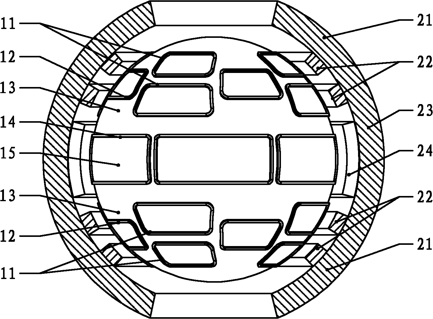
[0041] Specific implementation mode one, see figure 1 , 2 This embodiment will be described. The multi-degree-of-freedom magnetic levitation motor described in this embodiment is a spherical motor, which includes a rotating motor unit and a deflection and levitation motor unit,

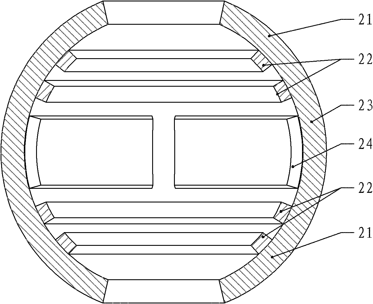
[0042] The rotating electrical machine unit is composed of a stator and a rotor, the stator includes an armature core 15 and a multi-phase armature winding, the rotor includes a rotor yoke 23 and a rotor permanent magnet 24, and the rotating electrical machine unit is an outer rotor structure;

[0043] The deflection and levitation motor unit includes a primary and a secondary, the primary comprises a deflection control winding, a levitation control winding and a primary iron core 13, the secondary yoke 21 includes a secondary yoke 21 and a secondary permanent magnet 22, and the deflection and levitation motor unit is the outer substructure,

[0044] The armature iron core 15 of the rotary motor un...

specific Embodiment approach 2

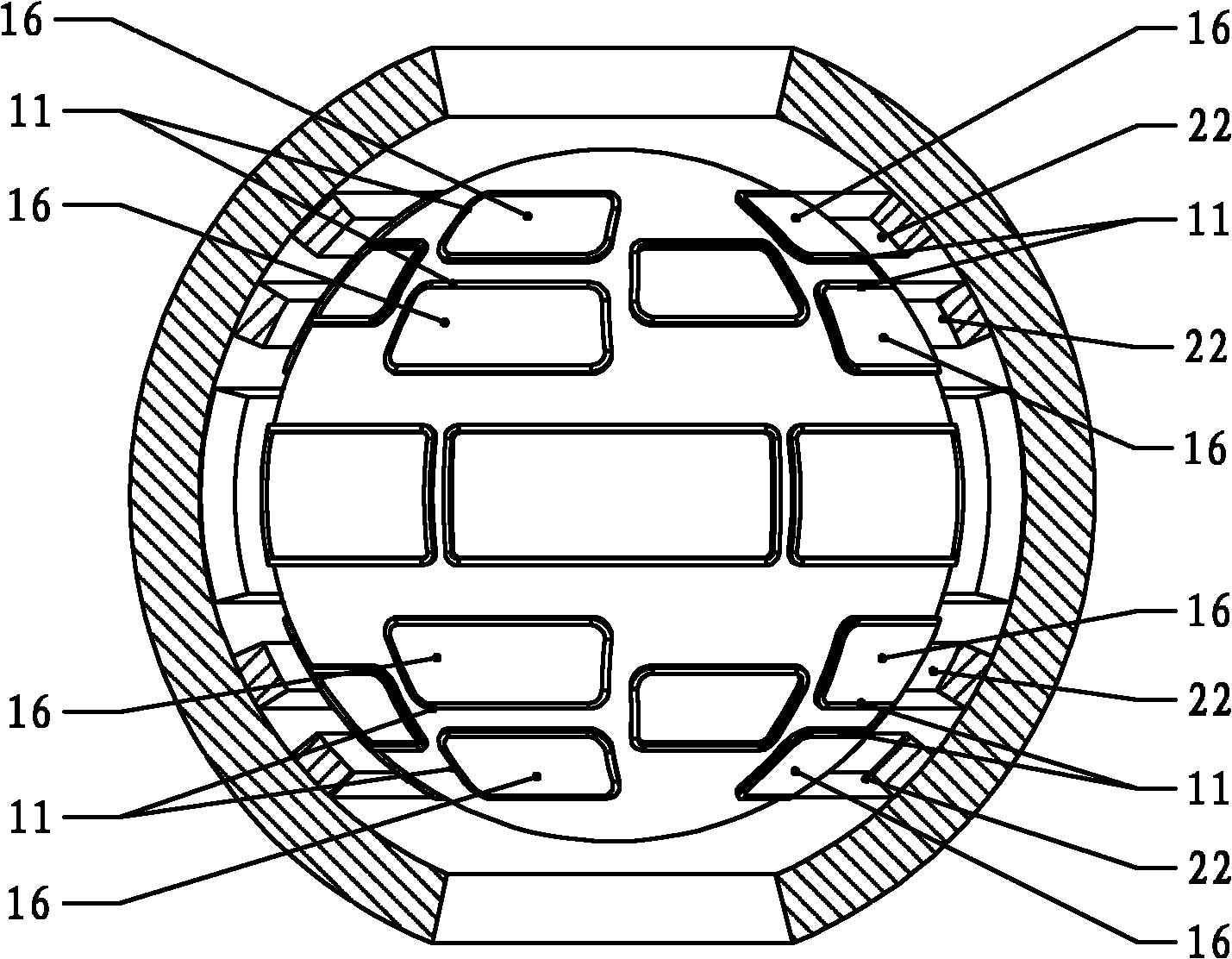
[0049] Embodiment 2. This embodiment is a further limitation of the multi-degree-of-freedom magnetic levitation motor described in Embodiment 1. In this embodiment, the effective side of each rotating armature coil 14 is embedded in the armature core 15 . Embedding the rotating armature coil 14 in the iron core can increase the magnetic field intensity generated by the coil, that is, when the same current flows through the coil, the magnetic field intensity generated by the coil will be greater after being embedded in the iron core.

specific Embodiment approach 3

[0050] Embodiment 3. This embodiment is a further limitation of the multi-degree-of-freedom magnetic levitation motor described in Embodiment 1. In this embodiment, each rotating armature coil 14 is embedded in an armature core 15 .


PUM


Abstract

The invention provides an MDOF (multiple-degree-of-freedom) magnetic suspension motor, belonging to the technical field of motors. A magnetic suspension technology is combined with an MDOF motor technology to design the MDOF magnetic suspension motor. A spherical type MDOF magnetic suspension motor, a cylinder type MDOF magnetic suspension motor and a flat plate type MDOF magnetic suspension motor are provided, wherein a stator and a rotor of a rotating machine unit of the spherical type MDOF magnetic suspension motor are fixedly connected with a deflection motor unit and a suspension motor unit mainly by a primary structure and a secondary structure; a stator and a rotor of a rotating machine unit of the cylinder type MDOF magnetic suspension motor are fixedly connected with primary structures and secondary structures of an axial thrust and suspension motor unit respectively; and a primary structure and a secondary structure of a bilateral linear motor unit of the flat plate type MDOF magnetic suspension motor are fixedly connected with a primary structure and a secondary structure of an oriented suspension motor unit respectively. The MDOF control windings of the three motors are independent mutually and are not coupled; the same secondary structure is used for the suspension control and the deflection control, thereby being simple in structure; and the rotors are supported by adopting a magnetic suspension way, thus the friction does not occur, the speed is high and the service life is long.

Description

technical field [0001] The invention relates to a multi-degree-of-freedom magnetic levitation motor, which belongs to the field of motors. Background technique [0002] For a long time, people have conducted extensive and in-depth research on the servo motor and its control system for single-degree-of-freedom motion, which has continuously improved the performance of the electric drive system with the servo motor as the core component. However, with the increasing complexity of mechanical systems, especially for precision devices that perform complex movements such as robots and manipulators, servo systems composed of single-degree-of-freedom motors often appear too complicated. For example, the manipulators used in engineering generally have more than three degrees of freedom of motion, and at least three single-degree-of-freedom motors and complex mechanical transmission mechanisms are required to complete the rotation function of the hand joints. This not only causes the...

Claims


Application Information

Patent Timeline
Patent Type & Authority Applications(China)
IPC IPC(8): H02N15/00
Inventor 寇宝泉张鲁张赫
Owner HARBIN INST OF TECH
Why Eureka
Try Eureka