Bearing box of heavy slurry pump and shafting transmission structure thereof

A transmission structure and bearing box technology, which is applied in the field of mechanical transmission, can solve the problems of difficult adjustment of the gap between the impeller and the flow-passing parts, difficulty in ensuring machining accuracy and coaxiality, and poor interchangeability of parts, so as to reduce the amount of processing and reduce leakage. Oil risk, effect of good sealing performance

Active Publication Date: 2011-11-16
XIANGYANG WU ER WU PUMP IND
View PDF6 Cites 10 Cited by
  • Summary
  • Abstract
  • Description
  • Claims
  • Application Information

AI Technical Summary

Problems solved by technology

[0004] In the prior art, the bearing box and its bracket structure of the heavy-duty slurry pump have large processing area, high processing cost, difficulty in ensuring processing accuracy and coaxiality, poor interchangeability of parts, high risk of oil leakage, and difficulty in adjusting the impeller and The purpose of the present invention is to solve the above-mentioned problems and disclose a heavy-duty slurry pump bearing box and its shaft transmission structure.

Method used


Image

  • Bearing box of heavy slurry pump and shafting transmission structure thereof
  • Bearing box of heavy slurry pump and shafting transmission structure thereof
  • Bearing box of heavy slurry pump and shafting transmission structure thereof

Examples


Embodiment Construction

[0026] specific implementation

[0027] Below in conjunction with accompanying drawing and embodiment the present invention will be further described:

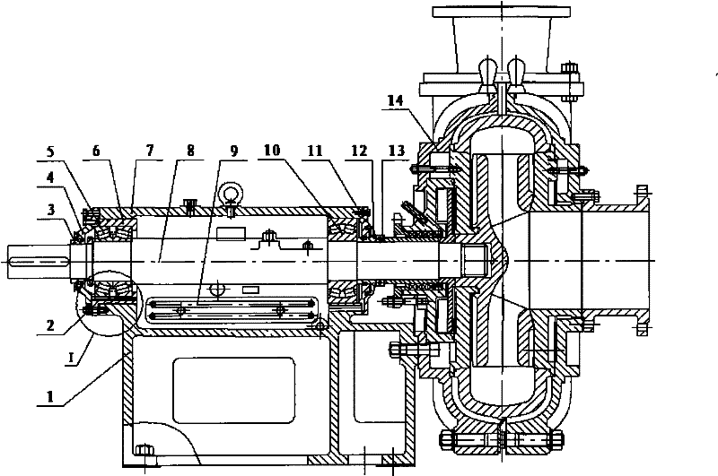
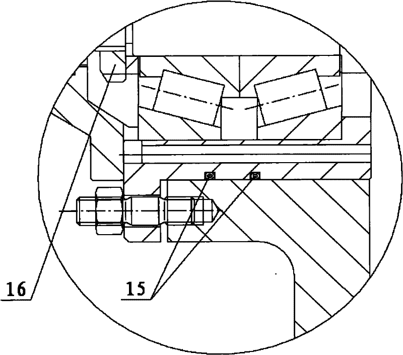
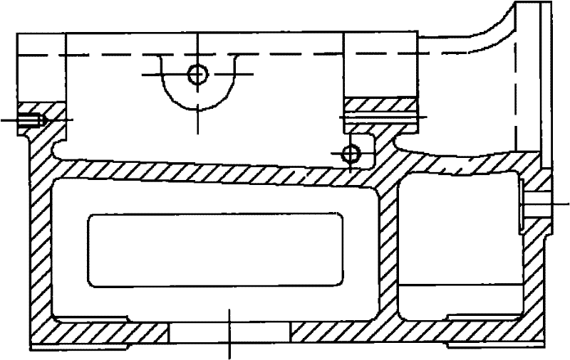
[0028] A heavy-duty slurry pump bearing box and its shaft transmission structure, which includes a pump shaft 8, a cooler 9, a front bearing cover 11, a rear bearing cover 4, a front dustproof plate 12, and a rear dustproof plate 3. It also includes bracket 17, bearing housing 20, second adjusting bolt 19, rear locking stud nut 18 and pressure ring 21; peripheral equipment includes: dismantling ring 13, flow-passing component 14; wherein, the structure diagram of bracket 17 is as follows Figure 10 , Figure 11 Shown, bracket 17 mainly bears radial force jointly with front, middle and rear three vertical stiffener plates and left and right two circular arc smooth design stiffeners, and the oil storage space has been canceled on bracket 17. The structural diagram of the bearing housing 20 is as follows: Figure 12 , Figure...


PUM


Abstract

The invention discloses a bearing box of a heavy slurry pump and a shafting transmission structure thereof and particularly relates to an integral bearing box of a horizontal abrasion-resistant slurry pump and a shafting transmission structure thereof, which belongs to the field of a mechanical transmission technique. The shafting transmission structure disclosed by the invention comprises a pumpshaft, a cooler, a front bearing gland, a rear bearing gland, a front dustproof disk, a rear dustproof disk, a carrier, a bearing box, a second regulating bolt, rear locking stud nuts and a compression ring. In order to reduce the machining area and matching area among a carrier body, a bearing bush and a carrier cover, the bearing bush and the carrier cover are cast into an integral; in order toconveniently regulate the gap between an impeller and an flow passage component, the arrangement of the second regulating bolt is optimized; and a second shaft regulating bolt is changed to be arranged between the rear lower end of the bearing box and the rear rib plate of the carrier, and the regulating space is enlarged, therefore thicker and longer bolts, studs and nuts can be adopted, therebyenlarging the regulating space. In the invention, the machining load can be reduced; the machining cost is lowered; the machining and finishing accuracy is improved; the oil leakage risk is reduced; and the coaxially of the bearing box and the carrier can be better guaranteed.

Description

technical field [0001] The invention relates to a bearing box and a shaft transmission structure of a heavy-duty slurry pump, in particular to an integral bearing box and a shaft transmission structure of a horizontal wear-resistant slurry pump, belonging to the technical field of mechanical transmission. Background technique [0002] Slurry pump is a kind of centrifugal pump that can transport the slurry containing large particle size impurities, or slurry containing granular abrasive and corrosive impurities. It is mainly used in metallurgy, petrochemical industry, mining, coal mine, building materials, light industry, Papermaking and other industries transport material (slag) slurry that contains particles and is corrosive. The transmission form of the horizontal slurry pump is mainly the bracket type transmission. The motor end can adopt various connection methods such as coupling, pulley or adding a hydraulic coupling. The structure is suitable for series or parallel c...

Claims


Application Information

Patent Timeline
Patent Type & Authority Applications(China)
IPC IPC(8): F04D29/046F04D29/044F04D7/04
Inventor 王军李烨韦家宁王爱兰王小锋杨银姜红霞
Owner XIANGYANG WU ER WU PUMP IND
Why Eureka
Try Eureka