Numerical-control drilling machine for machining inner blind hole of oil-production perforation gun tube body

A technology of CNC drilling machine and perforating barrel, which is applied in boring/drilling, metal processing equipment, drilling/drilling equipment, etc., can solve the problem of blind hole processing in the barrel that cannot be perforated, and improve the work efficiency , the effect of breaking the target easily

Active Publication Date: 2011-11-23
哈尔滨市东方刃具厂有限公司
View PDF6 Cites 11 Cited by
  • Summary
  • Abstract
  • Description
  • Claims
  • Application Information

AI Technical Summary

Problems solved by technology

[0003] The purpose of the present invention is to solve the problem that the existing technology cannot directly process the inner blind hole of the perforating gun barrel with small inner diameter, and provide a numerical control drilling machine for processing the blind hole in the oil production perforating gun barrel

Method used


Image

  • Numerical-control drilling machine for machining inner blind hole of oil-production perforation gun tube body
  • Numerical-control drilling machine for machining inner blind hole of oil-production perforation gun tube body
  • Numerical-control drilling machine for machining inner blind hole of oil-production perforation gun tube body

Examples


specific Embodiment approach 1

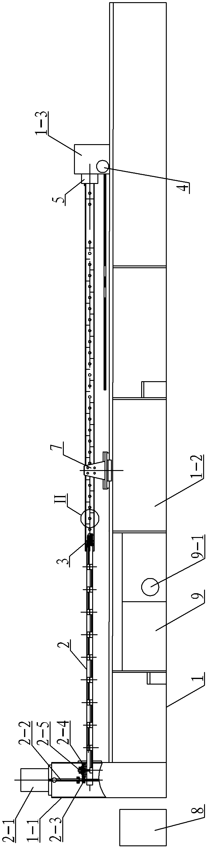
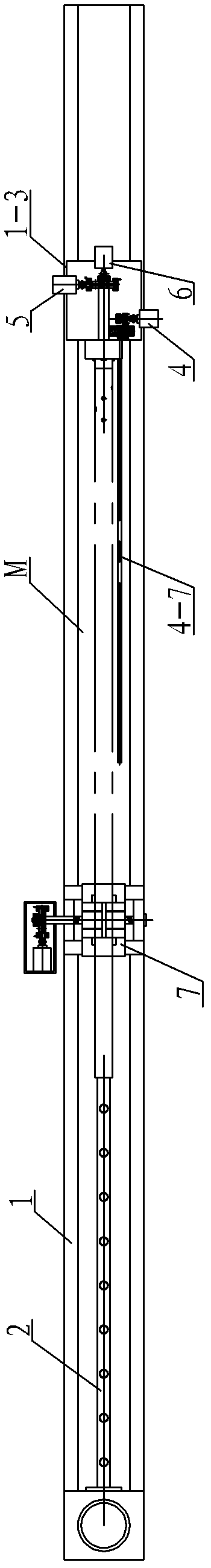
[0007] Specific implementation mode one: combine Figure 1 to Figure 11 Describe this embodiment, this embodiment comprises bed body 1, chain transmission mechanism 2, cutter head mechanism 3, longitudinal feed mechanism 4, chuck indexing mechanism 5, chuck clamping mechanism 6, support clamping mechanism 7, numerical control Device 8 and hydraulic control system 9. The bed body includes a headstock 1-1, a bed 1-2 and a feed box 1-3. The headstock 1-1 is arranged at one end of the head of the bed 1-2, and the feed box 1 -3 is arranged on the working table at the end of the bed 1-2, the hydraulic control system 9 is installed in the bed 1-2, the transmission motor 2-1 on the chain transmission mechanism 2 is fixed on the headstock 1-1, and the chain One end of the sprocket box 2-38 on the transmission mechanism 2 is fixed in the main shaft box 1-1, and the drill bit 3-7 on the cutter head mechanism 3 is connected with the secondary sprocket shaft 2-37 on the chain transmission ...

specific Embodiment approach 2

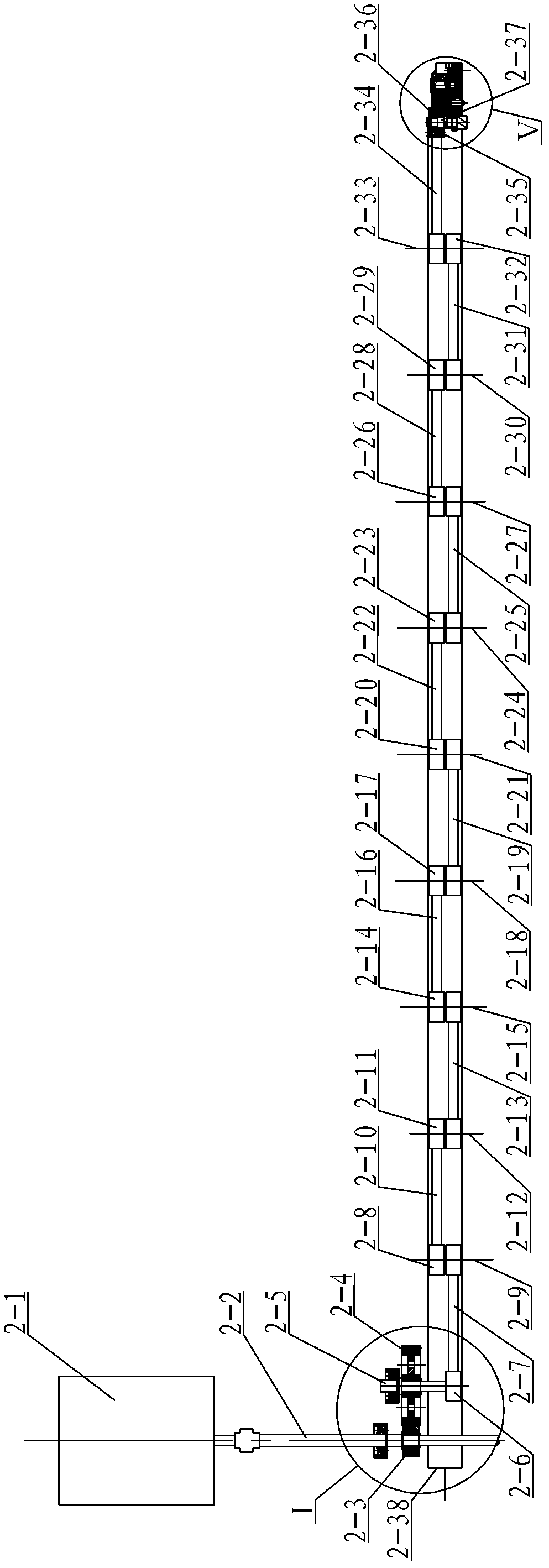
[0009] Specific implementation mode two: combination Figure 3 ~ Figure 5Describe this embodiment, the chain transmission mechanism 2 of this embodiment comprises transmission motor 2-1, transmission gear shaft 2-2, transmission main gear 2-3, transmission auxiliary gear 2-4, main sprocket shaft 2-5, main chain Wheel 2-6, the first chain 2-7, the first double row sprocket wheel 2-8, the first double row sprocket wheel shaft 2-9, the second chain 2-10, the second double row sprocket wheel 2-11, the second Two double-row sprocket shaft 2-12, the third chain 2-13, the third double-row sprocket 2-14, the third double-row sprocket shaft 2-15, the fourth chain 2-16, the fourth double-row sprocket 2 -17, the fourth double row sprocket shaft 2-18, the fifth chain 2-19, the fifth double row sprocket wheel 2-20, the fifth double row sprocket shaft 2-21, the sixth chain 2-22, the sixth double Row sprocket 2-23, sixth double row sprocket shaft 2-24, seventh chain 2-25, seventh double row...

specific Embodiment approach 3

[0010] Specific implementation mode three: combination Figure 5 and Figure 6 Describe this embodiment, the cutter head mechanism 3 of this embodiment comprises support base 3-1, hydraulic cylinder barrel 3-2, piston rod 3-3, spring 3-4, piston 3-5, drill bit 3-7, the second The bearing 3-8 and the limit screw 3-9, the hydraulic cylinder 3-2 are installed on the support base 3-1, and the support base 3-1 is provided with a piston rod thread corresponding to the inner cavity of the hydraulic cylinder 3-2 Groove 3-1-1, the piston rod 3-3 is set in the inner cavity of the hydraulic cylinder 3-2, and the end of the piston rod 3-3 corresponding to the piston rod thread groove 3-1-1 is set in the piston rod thread groove 3 -1-1, and the piston rod 3-3 is threadedly connected with the piston rod thread groove 3-1-1, the spring 3-4 is set on the piston rod 3-3, and the piston 3-5 is set on the hydraulic cylinder 3-2 between the inner wall of the cylinder and the spring 3-4, and the...


PUM

PropertyMeasurementUnit
thicknessaaaaaaaaaa

Abstract

The invention relates to a drilling machine for machining inner blind holes and in particular relates to a numerical-control drilling machine for machining an inner blind hole of an oil-production perforation gun tube body, and the drilling machine provided by the invention is used for solving the problem in the prior art fails that the inner blind hole of a perforation gun tube with a small inside diameter can not be directly machined. The rotation of a drill bit which is arranged on a cutter head mechanism is achieved by the transmission of a chain which is driven by a drive motor which is arranged on a chain transmission mechanism. The longitudinal feeding operation is achieved by the engagement of a feeding gear and a toothed rack which are driven by a feeding motor which is arranged on a longitudinal feeding mechanism through a feeding worm and a feeding worm wheel. The division of a chuck is achieved by the transmission of a division worm wheel and a division worm which are driven by a division motor which is arranged on a chuck division mechanism. The clamping of the chuck is achieved by driving a chuck clamping sleeve on a chuck clamping mechanism through a chuck clamping motor which is arranged on the chuck clamping mechanism. A numerical control device controls the transmission motor, the feeding motor, the division motor, the chuck clamping motor and a hydraulic control motor which is arranged on a hydraulic control system respectively. An oil inlet is connected with an oil supply pipe which is arranged on the hydraulic control system through an oil pipe. The numerical-control drilling machine provided by the invention is applied to machining the inner blind holes.

Description

technical field [0001] The invention relates to a drilling machine for processing inner blind holes. Background technique [0002] When oil drilling is completed, it is necessary to open the oil layer with a perforating gun. At present, perforation is based on the principle of high-efficiency energy-concentrating blasting. The cable is used to send the perforating gun to the part of the oil layer casing to be perforated, and the electric detonator is used to detonate the perforating bullet. The bullet is a high-efficiency gunpowder pressed into a dense, energy-gathering cone, covered with a copper skin. Gunpowder deflagration along the center of the conical surface instantly shoots through the oil layer casing wall and cement layer at a high speed of 8,000 meters per second and a high temperature jet flow above 2,000°C, and then penetrates 300 to 500 mm in the formation. Therefore, it is necessary to The inner blind hole is processed on the wall of the perforating gun barr...

Claims


Application Information

Patent Timeline
Patent Type & Authority Applications(China)
IPC IPC(8): B23B41/00B23B47/16B23B47/22B23Q16/02B23B31/02B23Q3/06
Inventor 由雨鑫
Owner 哈尔滨市东方刃具厂有限公司
Why Eureka
Try Eureka