Wireless energy transmission device based on self-resonant electromagnetic induction coupling

A wireless energy transmission, electromagnetic induction technology, applied in circuit devices, electromagnetic wave systems, electrical components, etc., can solve the problems of complex design, bulky, difficult to apply, etc., to achieve the effect of simple structure, long transmission distance, and small radiation

Inactive Publication Date: 2011-11-23
XIDIAN UNIV
View PDF4 Cites 11 Cited by
  • Summary
  • Abstract
  • Description
  • Claims
  • Application Information

AI Technical Summary

Problems solved by technology

The disadvantage of this technology is that two resonant coils are required, which is bulky and complex in design, making it difficult to apply in practice

Method used


Image

  • Wireless energy transmission device based on self-resonant electromagnetic induction coupling
  • Wireless energy transmission device based on self-resonant electromagnetic induction coupling
  • Wireless energy transmission device based on self-resonant electromagnetic induction coupling

Examples


Embodiment 1

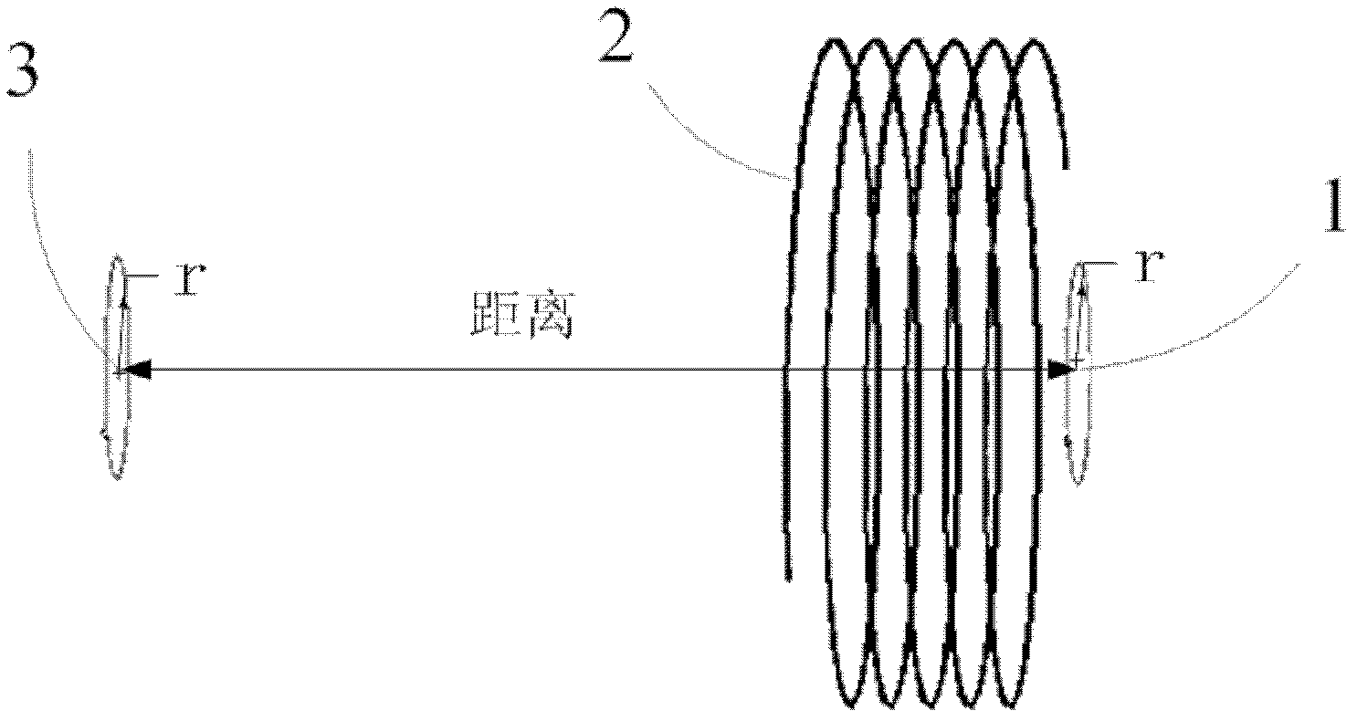
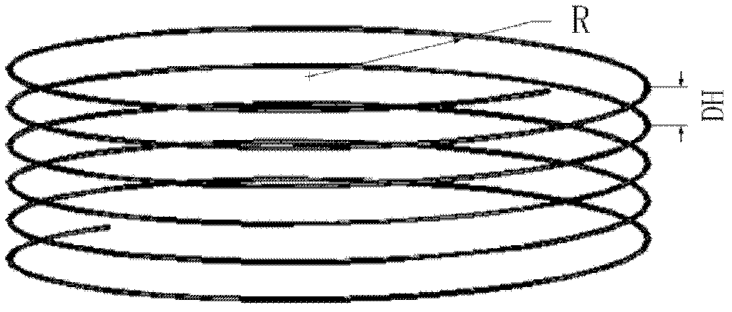
[0030] refer to figure 1 In the first embodiment of the present invention, the excitation part 1 and the load part 3 all use copper wires with a wire diameter of 4mm to make two single-turn ring coils with a radius of r=10cm, but are not limited to single-turn rings with the same radius. Shaped coils, for example, multi-turn loop coils or rectangular coils with different radii can also be used; resonant part 2 adopts such as figure 2 For the single tubular helical coil shown, the number of turns of the coil is n=5.5, the pitch is DH=3.6cm, the wire diameter is 4mm, the section radius is R=30cm, and the material is copper or silver. The working frequency of the tubular helical coil is f 0 By its own distributed inductance L S with distributed capacitance C S jointly decide, namely: In this embodiment, the operating frequency is f 0 =10.0±0.5MHz. The distance between the resonant part 2 and the excitation part 1 is 3.6cm, and it remains fixed; the distance between the ex...

Embodiment 2

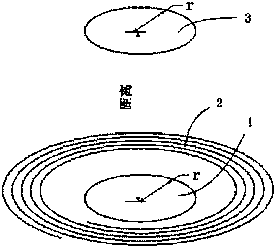
[0033] refer to image 3 , in the present invention, the excitation part 1 and the load part 3 all use copper wires with a wire diameter of 4mm to make two single-turn toroidal coils with a radius of r=6cm, but are not limited to single-turn toroidal coils, but are not limited to The single-turn toroidal coil with the same radius, for example, can also adopt multi-turn toroidal coils or rectangular coils with different radii; resonant part 2 of the present invention adopts such as Figure 4 The planar asymptote helical coil shown has n=5 turns, pitch DH=1cm, wire diameter 4mm, initial radius Rs=10cm, cut-off radius Re=15cm, material is copper, and its working frequency for f 0 =22.5±0.5MHz.

[0034] The distance between the resonant part 2 and the excitation part 1 is 1 cm and remains fixed; the distance between the load part 3 and the excitation part 1 can move freely within the range of 0 cm-20 cm, and the distance between the plane asymptotic helical coil and the load par...


PUM


Abstract

The invention discloses a wireless energy transmission device based on self-resonant electromagnetic induction coupling. The device mainly solves the problem of low energy transmission efficiency at a farther distance of the conventional electromagnetic induction coupling type wireless energy transmission device. The wireless energy transmission device based on the self-resonant electromagnetic induction coupling comprises an exciting part (1), a resonance part (2) and a load part (3), wherein the exciting part (1) is externally connected with a high-frequency oscillation circuit; the load part (3) is externally connected with a load circuit; the resonance part (2) adopts a single tubular spiral coil or a single planar asymptotic spiral coil and is positioned between the exciting part (1) and the load part (3); the exciting part (1) generates a high-frequency magnetic field to pass through the resonance part (2) and excites the resonance part (2) to generate resonance; and resonance energy is transmitted to the load part (3) to generate an induction electromotive force to transmit electric energy for external connection of the load circuit. The wireless energy transmission device based on the self-resonant electromagnetic induction coupling has the advantages of high efficiency, simple structure and low radiation and can be applied to wireless charging and power supplying of various kinds of electronic equipment.

Description

technical field [0001] The invention belongs to the technical field of wireless communication, and relates to wireless energy transmission, in particular to a wireless energy transmission device utilizing coil self-resonance to improve electromagnetic induction coupling. The device can be used in wireless charging and wireless power supply systems of various electronic products. When the transmission distance is fixed, the energy transmission efficiency can be improved by using the device. When the transmission efficiency is required to be constant, the energy transmission distance can be significantly increased. Background technique [0002] Since the discovery of the law of electromagnetic induction in 1840, people have begun to study wireless technology. Network-based communication technology has completed a leap from wired to wireless. However, the development of wireless energy transmission is extremely slow, so that the current Almost all charging or actual power trans...

Claims


Application Information

Patent Timeline
Patent Type & Authority Applications(China)
IPC IPC(8): H02J17/00H02J50/20
Inventor 李龙范迎春余世星
Owner XIDIAN UNIV
Why Eureka
Try Eureka