Single-stage boosting inverter with tap inductor

A tapped inductor and inverter technology, applied in the field of new energy power generation inverter, can solve problems such as easy resonance, intermittent input current, and little research, to solve the problem of waveform distortion, increase the DC bus voltage, avoid The effect of output waveform distortion

Inactive Publication Date: 2011-11-23
NANJING UNIV OF AERONAUTICS & ASTRONAUTICS
View PDF3 Cites 29 Cited by
  • Summary
  • Abstract
  • Description
  • Claims
  • Application Information

AI Technical Summary

Problems solved by technology

Since the capacitor voltage is 0 at start-up, there is a large inrush current at start-up, and it is easy to cause resonance during the start-up process, resulting in a large inrush current and inrush voltage, which may damage the inverter
[0016] (2) The bus voltage of the inverter bridge is lower than the capacitor voltage, and the voltage level of the capacitor cannot be fully utilized. If it is a high-voltage application, a high-voltage capacitor is required, and the volume is large
The voltage will drop, and the modulation algorithm

Method used


Image

  • Single-stage boosting inverter with tap inductor
  • Single-stage boosting inverter with tap inductor
  • Single-stage boosting inverter with tap inductor

Examples


Embodiment Construction

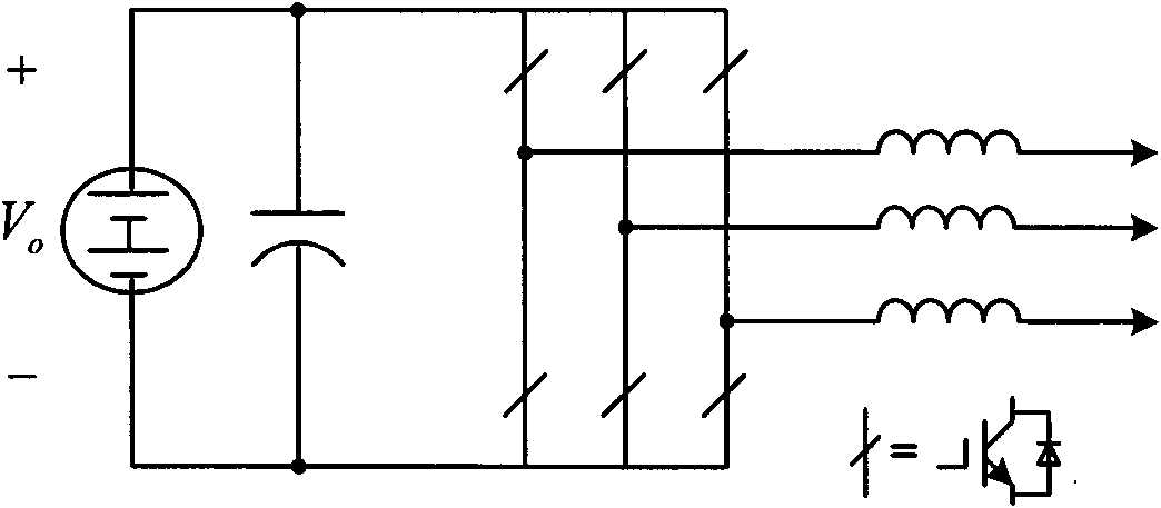
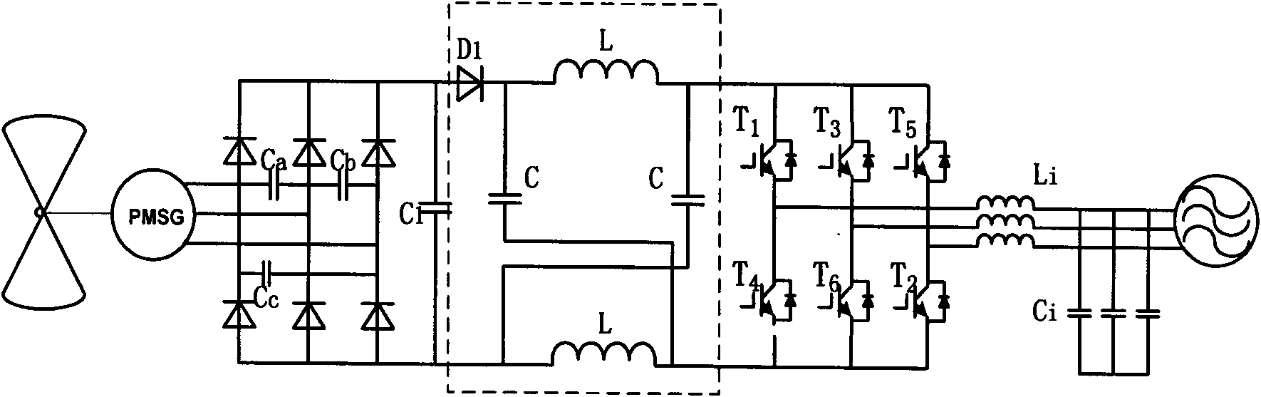
[0044] as attached Figure 5 As shown, the single-stage boost inverter topology of the present invention adds a boost network made up of passive devices before the traditional voltage-type inverter three-phase switch bridge (B): including a tapped inductor (Lt) , the first winding (N1) and the second winding (N2) of the tapped inductor (Lt) are forward connected in series, the terminal with the same name of the first winding (N1) is connected to the cathode of the first diode (D1), the first capacitor (C1 ), the opposite end of the first winding (N1) is connected to the anode of the second diode (D2), and at the same time connected to the same end of the second winding (N2), the anode of the first diode (D1) It is connected to one end of the inductor (L) and one end of the second capacitor (C2), the other end of the inductor (L) is connected to the positive pole of the power supply (Vi), and the other end of the second capacitor (C2) is connected to the third diode (D3 ), the...


PUM


Abstract

The invention discloses a single-stage boosting inverter with a tap inductor, which is shown in a figure described in the specification. The inverter comprises an inversion bridge (B) and a passive network. The passive network comprises an inductor (L), capacitors (C1 and C2), diodes (D1, D2 and D3) and the tap inductor (Lt). A first winding (N1) and a second winding (N2) of the tap inductor (Lt) are connected in series positively. According to the inverter disclosed by the invention, energy is stored in the tap inductor (Lt) by utilizing an ended zero vector state forbidden in the traditional voltage type inverter; the energy is combined with energy supplied by an input power supply in a non-ended zero vector state; and the combined energy is transmitted together to a middle bus so that the voltage of the bus is boosted. Therefore, the inverter can output alternating-current voltage, an amplitude value of which is higher than that of input voltage (Vi); the inverter can satisfy boosting requirements in different application situations by configuring the turn ratio of the tap inductor (Lt); and in the event of being applicable to an alternating-current input situation, the inverter can also realize a power factor correction (PFC) function.

Description

technical field [0001] The invention relates to a single-stage step-up inverter with a tapped inductor, which is especially suitable for a motor drive system in which a DC bus needs to be powered by a low-voltage step-up and a new energy power generation inverter application adapting to a large input voltage variation range. Background technique [0002] A traditional voltage source inverter such as the attached figure 1 As shown, there are usually the following limitations or deficiencies: [0003] (1) The AC load must be inductive or have to be connected in series with the AC power supply to enable the voltage source inverter to work normally. [0004] (2) The AC output voltage is limited to be lower than but not higher than the DC bus voltage. Therefore, for DC / AC power conversion, the traditional voltage source inverter is a step-down inverter. For DC / AC power conversion applications with low DC voltage and high AC output voltage, an additional DC / DC boost converter is...

Claims


Application Information

Patent Timeline
IPC IPC(8): H02M7/48H02M1/42H02M1/12
CPCY02B70/126Y02B70/10
Inventor 周玉斐黄文新胡育文
Owner NANJING UNIV OF AERONAUTICS & ASTRONAUTICS
Why Eureka
Try Eureka