Surface mount type power led bracket manufacturing method and product thereof

A LED bracket and surface mount technology, applied in the direction of electrical components, electrical solid devices, circuits, etc., can solve the problems of poor heat dissipation, poor heat resistance, and low yield of ordinary insulating boards, and achieve good light output and excellent durability. Effects of thermal performance and production cost reduction

Active Publication Date: 2011-12-07
FOSHAN NATIONSTAR OPTOELECTRONICS CO LTD +1
View PDF4 Cites 7 Cited by
  • Summary
  • Abstract
  • Description
  • Claims
  • Application Information

AI Technical Summary

Problems solved by technology

However, due to the disadvantages of poor heat dissipation and poor heat resistance of ordinary insulating boards, on the one hand, those skilled in the art generally believe that they are not suitable for the high heat dissipation requirements of power LED devices, and can only be used for low-power LED devices. Poor versatility; on the other hand, due to its poor heat resistance, problems such as delamination and deformation are prone to occur in the LED packaging die-bonding process, and the yield is low. Those skilled in the art generally believe that ordinary insulating boards are not suitable as power Packaging materials for LEDs

Method used


Image

  • Surface mount type power led bracket manufacturing method and product thereof
  • Surface mount type power led bracket manufacturing method and product thereof
  • Surface mount type power led bracket manufacturing method and product thereof

Examples


Embodiment 1

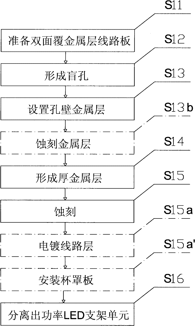
[0051] according to image 3 and Figure 4 Shown is Embodiment 1 of a method for manufacturing a power LED bracket provided by the present invention.

[0052] Such as image 3 Provided the process flow chart of the present embodiment, in conjunction with Figure 4 The schematic diagram of the process steps is given, and the specific manufacturing steps of this embodiment are described as follows.

[0053] Step S11) preparing a double-sided metal-clad circuit board:

[0054] Prepare a double-sided metal-clad circuit substrate 1, such as Figure 4 As shown in A, it includes a common insulating substrate 10 , a metal layer 1 1 covering the upper surface of the substrate, and a metal layer 2 12 covering the lower surface of the substrate 10 . The material of the substrate 10 has no special requirements, it is an ordinary insulating board, such as a PCB board, preferably, a cheap glass fiber cloth substrate, CEM-3 (3 grade composite epoxy material, English Composit Epoxy Mater...

Embodiment 2

[0074] according to Figure 5 and Figure 6 Shown is Embodiment 2 of a method for manufacturing a power LED bracket provided by the present invention.

[0075] Such as Figure 5 Provided the process flow chart of the present embodiment, in conjunction with Figure 6 The schematic diagram of the process steps is shown, and the specific manufacturing steps of this embodiment are described as follows.

[0076] Step S21) preparing a double-sided metal-clad circuit board:

[0077] Prepare a double-sided metal-coated circuit substrate 2, including an ordinary insulating substrate 20, a metal layer 21 covering the upper surface of the substrate, and a metal layer 2 22 covering the lower surface of the substrate; the material of the substrate 20 has no special requirements , is an ordinary insulating board, such as a PCB board, preferably, a cheap glass fiber cloth substrate (FR-4), CEM-3 (3-level composite epoxy material, English Composit Epoxy Material Grade-3), CEM -1 (Class 1...

Embodiment 3

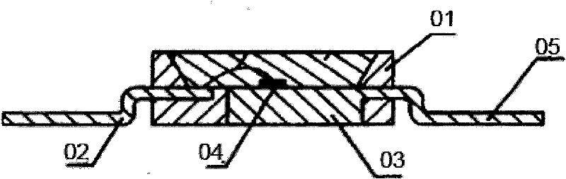
[0098] according to Figure 7 As shown, a power LED bracket provided by the present invention has a structure including: a double-sided metal-clad circuit board is a bracket substrate 3, at least one through hole 31 is arranged on the bracket substrate 3, and a through hole 31 The positive and negative electrodes 32 on both sides and the chip placement portion 351 at the bottom of the through hole 31 . Wherein, the support substrate 3 is composed of a metal layer 33, a metal layer 2 34 and an insulating substrate placed between the two metal layers; preferably, the positive or negative electrodes 32 each include at least one through The small electrode through hole 321 of the support substrate 3 is provided with a conductive layer 322 or filled with a conductive material (not marked) on the inner wall of the small electrode through hole 321; surrounding, the lead connecting portion 331 for welding metal wires, and the positive and negative electrode layer 1 332 located on bot...


PUM


Abstract

The invention relates to a method for manufacturing surface mounting type power LED (light emitting diode) support and a product thereof. The method comprises the following steps: 1) preparing a circuit board with a double-faced coated metal layer; 2) forming a hole; 3) arranging a hole-wall metal layer; 4) increasing the thickness of the metal layer; 5) etching the metal layer; 6) separating thepower LED support unit. According to the invention, the existing technical bias is overcome and the common insulation board is utilized as a substrate of the power LED support, thus the method provided by the invention has the advantages of simple process method and high production efficiency. The invention also provides a surface mounting type power LED support manufactured by the method provided by the invention. The LED support is structurally characterized in that the circuit board with the double-faced coated metal layer is utilized as a substrate of the support, and the substrate is provided with a hole, a first support line layer and a second support line layer which form the surface mounting type power LED support. The product manufactured by the method provided by the invention has the advantages of unique structure design, high reliability, good light emergent performance, good heat-dissipating effect, wide application scope, strong universality and outstanding technical effect, and is applicable to industrial and batch production.

Description

technical field [0001] The invention relates to a method for manufacturing an LED bracket applied to an LED device and a product thereof, in particular to a method for manufacturing a surface mount type power LED device bracket and a product thereof. Background technique [0002] Semiconductor lighting is known as the fourth-generation lighting source, and it is gradually popularized and applied to the field of general lighting. Among them, power light-emitting diodes (power LEDs) are popular in the market for their high brightness and high power. There are two types of brackets for conventional power LEDs: PLCC type (plastic led chip carrier, plastic lead chip carrier) and ceramic substrate. [0003] as attached figure 1 Shown is a schematic diagram of the structure of the PLCC-type stent in the prior art. The PLCC-type bracket is a plastic shell 01 with a reflective cavity structure that wraps a metal lead frame 02. The metal lead frame 02 has a chip placement part 03 c...

Claims


Application Information

Patent Timeline
Patent Type & Authority Applications(China)
IPC IPC(8): H01L33/62
CPCH01L2224/48247H01L2224/48091H01L2924/00014
Inventor 余彬海孙百荣李伟平夏勋力李程龙孟华梁丽芳
Owner FOSHAN NATIONSTAR OPTOELECTRONICS CO LTD
Why Eureka
Try Eureka