A method of increasing light absorption of solar cells

A solar cell and light absorption technology, applied in the field of solar energy applications, to achieve the effects of low cost, fully compatible production process and abundant reserves

Inactive Publication Date: 2011-12-14
ZHEJIANG UNIV
View PDF6 Cites 10 Cited by
  • Summary
  • Abstract
  • Description
  • Claims
  • Application Information

AI Technical Summary

Problems solved by technology

However, the above method can only achieve the anti-reflection function in a narrow wavelength region and a small range of incident angle changes

Method used


Image

  • A method of increasing light absorption of solar cells
  • A method of increasing light absorption of solar cells
  • A method of increasing light absorption of solar cells

Examples


Embodiment 1

[0036] Disperse zinc oxide nanoparticles with a particle diameter of 80-100nm in water to form a solution with a volume concentration of 0.8% zinc oxide nanoparticles; then apply the solution on the surface by spin coating at a speed of 350rad / min On the light-receiving surface of the monocrystalline silicon solar cell, zinc oxide nanoparticles are uniformly dispersed on the light-receiving surface of the monocrystalline silicon solar cell; finally, the monocrystalline silicon solar cell coated with zinc oxide nanoparticles is naturally air-dried in the air.

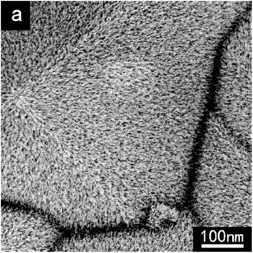
[0037] The composition and structure of the product obtained above were characterized, and it can be seen from the XRD spectrum and scanning electron microscope photos that a layer of zinc oxide nanoparticles with a particle diameter of 80-100 nm grows on the light-receiving surface of the single crystal silicon solar cell.

[0038] The schematic diagram of its product structure is shown in figure 1 As shown, a layer of ...

Embodiment 2

[0040] Disperse titanium dioxide nanoparticles with a particle diameter of 60-80nm in water to form a solution with a volume concentration of 0.5% of titanium dioxide nanoparticles; uniformly dispersed on the light-receiving surface of the polycrystalline silicon solar cell; finally, the polycrystalline silicon solar cell coated with titanium dioxide nanoparticles is naturally air-dried in the air.

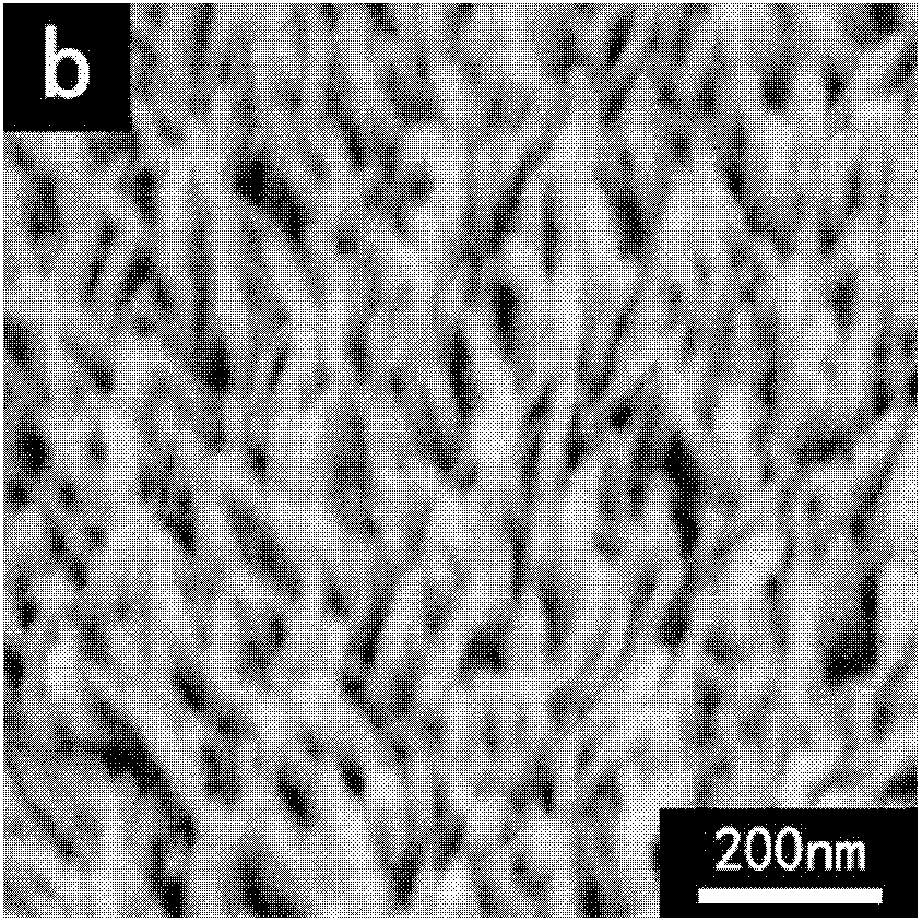
[0041] The composition and structure of the product obtained above were characterized, and it can be seen from the XRD spectrum and scanning electron microscope photos that a layer of titanium dioxide nanoparticles with particle diameters of 60-80 nm grows on the light-receiving surface of the polycrystalline silicon solar cell.

Embodiment 3

[0043] Disperse tin dioxide nanoparticles with a particle diameter of 60-80nm in water to form a solution with a volume concentration of 0.5% tin dioxide nanoparticles; then apply the solution by spin coating at a speed of 350rad / min Cover the light-receiving surface of the thin-film solar cell, so that the tin dioxide nanoparticles are uniformly dispersed on the light-receiving surface of the thin-film solar cell; finally, the thin-film solar cell coated with the tin dioxide nano-particle is naturally air-dried in the air.

[0044]The composition and structure of the product obtained above were characterized, and it can be seen from the XRD spectrum and scanning electron microscope photos that a layer of tin dioxide nanoparticles with a particle diameter distribution of 60-80 nm grows on the light-receiving surface of the thin-film solar cell.


PUM


Abstract

The invention discloses a method for increasing the light absorption of a solar cell, comprising: growing a nanostructure of a wide-bandgap oxide on the light-receiving surface of the solar cell, the wide-bandgap oxide being zinc oxide, titanium dioxide or tin dioxide, The nanostructure is a nanoparticle with a diameter of 10-100 nm or a nano-rod array with a single nano-rod length of 30-300 nm. The method for increasing the light absorption of the solar cell can significantly reduce the light reflection loss in a wide solar spectrum range, so that the efficiency of the solar cell is significantly improved. The method of the invention has simple process, low energy consumption, is fully compatible with the existing solar cell production process, and is suitable for large-scale industrialization.

Description

technical field [0001] The invention belongs to the field of solar energy applications, in particular to a method for increasing light absorption of solar cells. Background technique [0002] How to effectively reduce the reflectivity of solar cells and increase their light absorption is one of the key factors to improve the efficiency of solar cells. In the existing solar cell manufacturing process, most of the cell surface is textured first, and then a layer of silicon nitride film with a thickness of 80-100 nm is deposited on the textured surface as an anti-reflection film. In addition, some other wide bandgap thin film materials, such as titanium dioxide, silicon dioxide, etc., can also achieve better anti-reflection effects, see the literature M.A.Green, in: Silicon Solar Cells: Advanced Principles and Practice, Bridge, Sydney, 1995. There are also some reports using a multilayer film structure for antireflection. However, the above method can only realize the anti-re...

Claims


Application Information

Patent Timeline
Patent Type & Authority Applications(China)
IPC IPC(8): H01L31/18H01L31/0216B82Y20/00
CPCY02P70/50
Inventor 余学功雷东杨德仁
Owner ZHEJIANG UNIV
Why Eureka
Try Eureka