Full-bridge rectification-DC push-pull inverter ac-dc converter

An AC-DC, DC push-pull technology, applied in the direction of converting DC power input to DC power output, AC power input converting to DC power output, and irreversible AC power input converting to DC power output, etc. It can solve the problem of low feasibility. , high control difficulty, complex structure and other problems, to achieve the effect of economical and practical, simplified circuit structure, small system volume

Inactive Publication Date: 2011-12-21
SHANGHAI JIAO TONG UNIV
View PDF4 Cites 14 Cited by
  • Summary
  • Abstract
  • Description
  • Claims
  • Application Information

AI Technical Summary

Problems solved by technology

[0005] WANG JUN et al., "Smart Grid Technology". IEEE Trans. on Industry Electronics Magazine (Industrial Electronics Magazine). June 2009. Documented a "Power Electronics Transformer Technology Ba

Method used


Image

  • Full-bridge rectification-DC push-pull inverter ac-dc converter
  • Full-bridge rectification-DC push-pull inverter ac-dc converter
  • Full-bridge rectification-DC push-pull inverter ac-dc converter

Examples


Embodiment 1

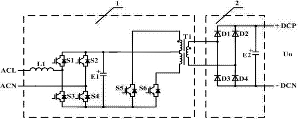
[0025] like figure 1 As shown, this embodiment provides a full-bridge rectification-DC push-pull inverter AC-DC converter, including: step-down circuit 1 and a rectifier circuit 2 connected thereto, wherein: step-down circuit 1 Convert high-voltage power frequency AC voltage into low-voltage high-frequency AC voltage. In the rectifier circuit 2, the low-voltage high-frequency AC voltage is converted into a low-voltage DC voltage, and the impedance conversion circuit can be connected in series in the subsequent stage to obtain linear input impedance and linear grid-side impedance to ensure a good grid-side power factor.

[0026] The step-down circuit 1 includes a sequentially connected boost inductor L1, a single-phase input rectifier (shown as S1 to S4 in the figure), an input filter capacitor E1, and a push-pull converter for AC chopping (S5 and S6 in the figure). shown) and high-frequency transformer T1 for step-down.

[0027] The boost inductor L1 used in the step-down ...

Embodiment 2

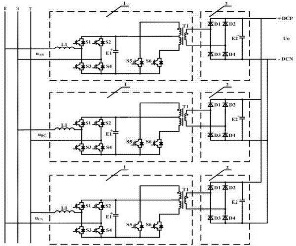
[0038] like figure 2 As shown, a schematic diagram of a three-phase input and output parallel full-bridge rectifier-DC push-pull inverter AC-DC converter. each of them Full-bridge rectification-DC push-pull inverter AC-DC converter The input terminals of the three-phase alternating current are respectively connected to any two phases, the three groups Full-bridge rectification-DC push-pull inverter AC-DC converter The output terminals are connected in parallel and output DC voltage.

[0039] This embodiment can avoid excitation saturation of the transformer and support greater power output.

Embodiment 3

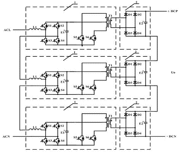
[0041] like image 3 As shown, a schematic diagram of an AC-DC converter with a full-bridge rectifier-DC push-pull inverter in series with input and output in series. consists of three groups of the same structure Full-bridge rectification-DC push-pull inverter AC-DC converter Composition, the three groups Full-bridge rectification-DC push-pull inverter AC-DC converter The input ends are connected in series, and the output ends are connected in series to output DC voltage.

[0042] This embodiment can avoid excitation saturation of the transformer, and realize high voltage input and greater power output.

[0043] After the device adopts the step-down circuit and the rectifier circuit, it can make the grid side of the power electronic converter work at the unit power factor without the need of the rear-stage series impedance conversion circuit, and eliminate the pollution of the harmonic current to the grid, which is conducive to simplifying the circuit design. , redu...


PUM


Abstract

The invention discloses a full-bridge rectification-DC push-pull inverter AC-DC converter in the technical field of power electronic conversion, which includes a step-down circuit and a rectifier circuit connected in series in sequence, and the step-down circuit converts the high voltage through a single-phase full-control rectification circuit The power frequency AC voltage is converted into high-voltage DC voltage, and then converted into high-voltage and high-frequency pulsed AC voltage through a push-pull converter, and the voltage is stepped down by a transformer to obtain low-voltage and high-frequency pulsed AC voltage; the rectifier circuit rectifies the low-voltage and high-frequency pulsed AC voltage, The low-voltage DC voltage is obtained, and then filtered by the output filter capacitor to obtain a stable DC output. The latter stage of the circuit can be connected in series with an impedance conversion circuit to obtain a linear input impedance, and after reflection to the high-voltage AC power grid, the linear input impedance and unit input power factor of the grid side can be obtained. The invention realizes the conversion of high-voltage AC voltage to low-voltage DC voltage through a step-down circuit and a rectifier circuit, and has the advantages of fewer power devices, simple overall structure and more perfect overall performance.

Description

technical field [0001] The invention relates to a device in the technical field of power electronic conversion, in particular to an AC-DC converter of full-bridge rectification-DC push-pull inverter. Background technique [0002] Power electronic transformers are mainly composed of power electronic converters, high-frequency transformers and controllers. These include: the power electronic converter of high-frequency and high-power power electronic devices such as IGBT or IGCT is the core of the power electronic transformer, and its function is to complete the frequency and amplitude conversion of electric energy; the function of the high-frequency transformer is isolation and voltage transformation; control The function of the inverter is to realize the control of power conversion, voltage stability and power quality. [0003] After searching the existing technology, it was found that Chinese patent application No. 02139030.4, publication date: 2003.03.12, recorded a "powe...

Claims


Application Information

Patent Timeline
IPC IPC(8): H02M7/162H02M7/17H02M3/335
Inventor 马红星李华武曹中圣杨喜军
Owner SHANGHAI JIAO TONG UNIV
Why Eureka
Try Eureka