Method for producing powder for dust core, powder core using powder for powder core produced by the method for producing powder for powder core, and apparatus for producing powder for dust core

Powder magnetic core, technology for production method, applied to production of powder for powder magnetic core, powder core using powder for powder magnetic core produced by the production of powder for powder magnetic core, and powder for powder magnetic core In the field of manufacturing equipment, it can solve the problems of high iron loss hysteresis loss and insufficient insulation of the contact part of iron powder 102

Inactive Publication Date: 2011-12-21
TOYOTA JIDOSHA KK
View PDF13 Cites 4 Cited by
  • Summary
  • Abstract
  • Description
  • Claims
  • Application Information

AI Technical Summary

Problems solved by technology

However, if the siliconized layer 104 is thin or the silicon element concentration in the siliconized layer 104 is low, the contact portion of the iron powder 102 cannot be sufficiently insulated, and the iron loss (mainly hysteresis loss and eddy current loss) becomes high.

Method used


Image

  • Method for producing powder for dust core, powder core using powder for powder core produced by the method for producing powder for powder core, and apparatus for producing powder for dust core
  • Method for producing powder for dust core, powder core using powder for powder core produced by the method for producing powder for powder core, and apparatus for producing powder for dust core
  • Method for producing powder for dust core, powder core using powder for powder core produced by the method for producing powder for powder core, and apparatus for producing powder for dust core

Examples


no. 1 approach

[0069]

[0070] Figure 14 It is a figure which shows the cross section of the powder 28 for powder magnetic cores.

[0071] The powder 28 for powder magnetic core forms a siliconized layer 25 on the surface of the iron powder 24 through the redox reaction of the carbon-iron metal powder 21 and the silicon dioxide powder 22 (an example of the powder for siliconizing) to ensure the protection of the iron. Insulation of powder 24 (an example of soft magnetic metal powder). Furthermore, the silicon coating layer 27 is formed in the dust core powder 28 so as to cover the surface of the iron powder 24, thereby further improving insulation.

[0072]

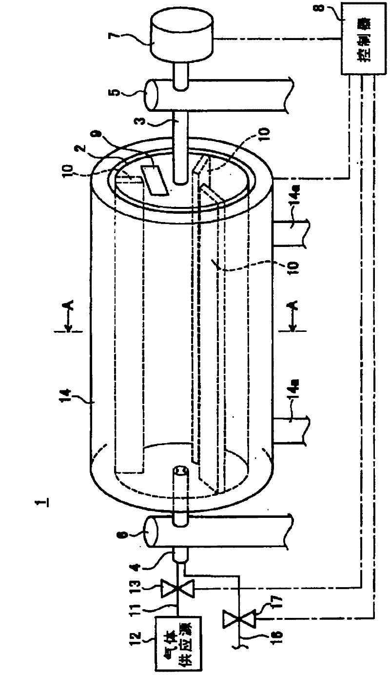
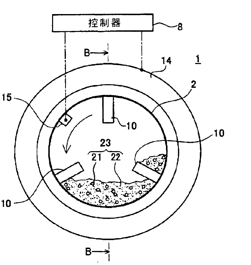
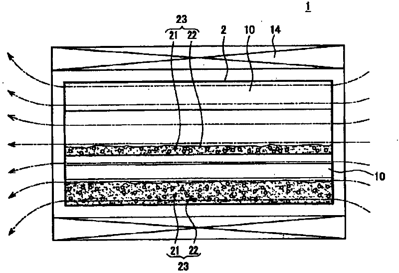
[0073] figure 1 It relates to the first embodiment of the present invention and is a schematic configuration diagram of a dust core powder manufacturing apparatus. figure 2 yes figure 1 AA sectional view of the rotary furnace shown. image 3 yes figure 2 The BB cross-sectional view of the rotary furnace is shown, and the ...

Embodiment

[0099] Figure 15 It is a figure which shows the conditions of the siliconizing process in a comparative example and an Example.

[0100] In Examples, siliconizing treatment was performed under the following conditions. 95 to 97% by weight of 1.5% by weight carbon steel powder (iron powder) with an average particle size of 150 μm to 212 μm, and 3 to 5% by weight of silica powder with an average particle size of 50 nm and a specific gravity of 2.2. The resulting mixed powder is fed into a rotary furnace made of ceramics, and then the rotary furnace is supplied with argon (Ar) and 30% hydrogen (H 2 ) at the same time as the mixed gas, start to exhaust. And a current of 100 MHz is supplied to the coil. After confirming that the iron powder was heated to a processing temperature of 1000° C. by a temperature sensor, the rotary furnace was rotated at a rotation speed of 25 rpm while supplying a current of 100 MHz to the coil. After 1 hour of processing time had elapsed in this s...

no. 2 approach

[0112] Next, a second embodiment of the present invention will be described. Figure 18 It is a schematic configuration diagram of a dust core powder manufacturing apparatus 51 relating to the second embodiment of the present invention.

[0113] The dust core powder manufacturing apparatus 51 of this embodiment has the same configuration as that of the first embodiment except for the coil 52 . Here, description will be made focusing on configurations different from those of the first embodiment, and the same configurations as those of the first embodiment will be given the same reference numerals as in the first embodiment in the drawings, and descriptions will be appropriately omitted.

[0114] The powder manufacturing apparatus 51 for dust magnetic cores has coils 52 formed by winding electric wires in a cylindrical shape arranged so as to surround the lower portion of the rotary furnace 2 from four directions. The coil 52 preferably heats half or less of the rotary furnace...


PUM

PropertyMeasurementUnit
diameteraaaaaaaaaa
melting pointaaaaaaaaaa

Abstract

Disclosed is a method for producing powder for a dust core capable of improving the quality and productivity of powder for a dust core, and which prevents formation of secondary particles when siliconizing. Also disclosed is a dust core that uses powder for a dust core produced using said method for producing powder for a dust core, and a device for producing powder for a dust core. In order to achieve same, only the soft magnetic metal powder (21) of a mixed powder (23) comprising soft magnetic metal powder (21) and powder for siliconizing containing silicon dioxide (22) is induction heated,which causes a heat transfer from the surface of the soft magnetic metal powder (21) to the powder for siliconizing (22), elemental silicon to detach from the powder for siliconizing (22), and the elemental silicon to be diffusion coated onto the surface of the soft magnetic metal powder (21), thereby forming a siliconized layer.

Description

technical field [0001] The present invention relates to a powder core powder production method for producing powder core powder, a powder core using the powder core powder produced by the powder core powder production method, and powder core powder production device. Background technique [0002] Powder cores are produced by forming powder cores containing soft magnetic metal powder with powder pressure. Dust cores have many advantages over core materials made of laminated electrical steel sheets. For example, they have magnetic properties with less high-frequency loss (hereinafter referred to as "iron loss") depending on the frequency; shape change; and low cost of materials, etc. Such a dust core is applied to, for example, a stator core or a rotor core of a drive motor of a vehicle, a reactor core constituting a power conversion circuit, and the like. [0003] For example, if Figure 19 As shown, the dust core powder 101 is subjected to a siliconizing treatment in whic...

Claims


Application Information

Patent Timeline
Patent Type & Authority Applications(China)
IPC IPC(8): B22F1/02B22F1/00B22F1/16
CPCC22C2202/02C22C33/0271B22F3/003B22F2999/00B22F1/02F27B7/16F27B7/34F27B7/42F27D11/06F27D2099/0015Y02P10/25B22F1/16B22F1/00B22F2202/05B22F2202/00B22F2201/00H01F1/33H01F1/24H01F3/08
Inventor 杉山昌挥山口登士也大平翔太
Owner TOYOTA JIDOSHA KK
Why Eureka
Try Eureka