

A kind of decorative material and preparation method thereof
A decorative material and decorative film technology, applied in chemical instruments and methods, metal material coating process, vacuum evaporation coating and other directions, can solve the problem of single color of decorative film layer, and achieve rich color, uniform color and strong metal texture. Effect
- Summary
- Abstract
- Description
- Claims
- Application Information
AI Technical Summary
Problems solved by technology
Method used
Image

Examples
preparation example Construction
[0015] The preparation method of the decorative material provided by the present invention comprises the steps of forming a decorative film layer and a metallized film layer on a base material in sequence under the condition of magnetron sputtering, and applying power on the magnetron target to sputter the target material on the magnetron target. The target material is at least one of titanium, titanium-aluminum, chromium, tungsten and stainless steel to form a decorative film layer and a metallized film layer plated on the substrate in turn. kind.
[0016] According to the preparation method of the decorative material of the present invention, the magnetron target is preferably a paired target structure, and one or several pairs of magnetron targets can be used as required. Each pair of magnetron targets is powered by one power supply and two magnetron targets. The targets are each connected to one pole of the power source and are insulated from the entire vacuum chamber. Th...
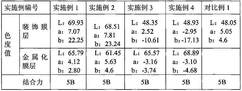
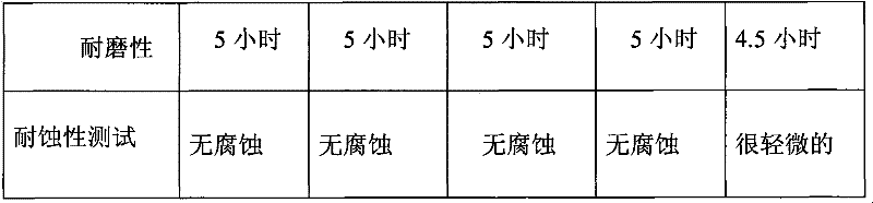
Embodiment 1
[0030] This example illustrates the decorative material of the present invention and its preparation method.
[0031] The base material is stainless steel (model 316L) workpiece
[0032] 1. Pretreatment
[0033] (1) Mechanical polishing
[0034] Using the polishing machine (JM-101 model) produced by Dongguan Jingmi Machinery Equipment Co., Ltd. and the yellow medium-coarse polishing paste (SBT-600 model) produced by Jiangmen Jie Lixin Polishing Materials Co., Ltd. The polishing wheel at 2840 rpm The stainless steel workpiece was rough-polished for 10 minutes at the rotational speed, and then fine-polished for 10 minutes at a polishing wheel speed of 2840 rpm with a white fine-polishing ointment (model SBW-804).
[0035] (2) Ultrasonic cleaning
[0036] The above-mentioned polished workpiece was immersed in normal temperature dewaxing water, degreasing powder solution and deionized water at 70° C. for ultrasonic cleaning in sequence. Among them, dewaxing water and degreasin...
Embodiment 2
[0052] This embodiment illustrates the coating material of the present invention and its preparation method.
[0053] The base material is titanium alloy (type TA2) workpiece
[0054] 1. Pretreatment
[0055] (1) Mechanical polishing
[0056] Using the polishing machine (JM-101 model) produced by Dongguan Jingmi Machinery Equipment Co., Ltd. and the yellow medium-coarse polishing paste (SBT-600 model) produced by Jiangmen Jie Lixin Polishing Materials Co., Ltd. The polishing wheel at 2840 rpm The titanium alloy workpiece was rough-polished for 10 minutes at the rotational speed, and then fine-polished for 10 minutes at a polishing wheel speed of 2840 rpm with a white fine-polishing ointment (model SBW-804).
[0057] (2) Drawing
[0058] The polishing machine (JM-101 model) produced by Dongguan Jingmi Machinery Equipment Co., Ltd. was used, and the red fine throwing ointment (555-10 model) produced by Shenzhen Hongfang Guanhua Technology Co., Ltd. was used at the speed of 14...
PUM
| Property | Measurement | Unit |
|---|---|---|
| Thickness | aaaaa | aaaaa |
| Thickness | aaaaa | aaaaa |
| Thickness | aaaaa | aaaaa |
Abstract
Description
Claims
Application Information