A Fully Differential Capacitance Readout Circuit with Cross Sampling and Double Summing of Charges

A capacitive readout and fully differential technology, which is applied in the direction of measuring devices, instruments, steering sensing equipment, etc., can solve the problems of increasing system area and power consumption, complicating temperature compensation circuits and methods, etc., to eliminate common-mode voltage drift, increase Large system dynamic range, the effect of suppressing mistuning

Inactive Publication Date: 2011-12-28
INST OF ELECTRONICS CHINESE ACAD OF SCI
View PDF5 Cites 23 Cited by
  • Summary
  • Abstract
  • Description
  • Claims
  • Application Information

AI Technical Summary

Problems solved by technology

Because the minimum signal amplitude that the sensor system can detect is determined by the noise of the sensor and its readout circuit, among which the noise of the readout circuit (including 1 / f noise and thermal noise, etc.) accounts for the main part, which is the primary factor restricting the detection accuracy of the sensor. Therefore, exploring the theory and method of eliminating and suppressing circuit noise has become a necessary way and method to improve the detection accuracy and resolution of capacitive sensors. There is also a mismatch, so the readout circuit needs to use a certain method to compensate or suppress the error caused by device mismatch; in addition, due to the influence of temperature and environmental factors, device parameters, power supply voltage and common mode voltage And other parameters will drift accordingly. The traditional capacitance readout circuit is very sensitive to temperature drift, and its corresponding temperature compensation circuit and method are also very complicated, which increases the area and power consumption of the system.

Method used


Image

  • A Fully Differential Capacitance Readout Circuit with Cross Sampling and Double Summing of Charges
  • A Fully Differential Capacitance Readout Circuit with Cross Sampling and Double Summing of Charges
  • A Fully Differential Capacitance Readout Circuit with Cross Sampling and Double Summing of Charges

Examples


Embodiment Construction

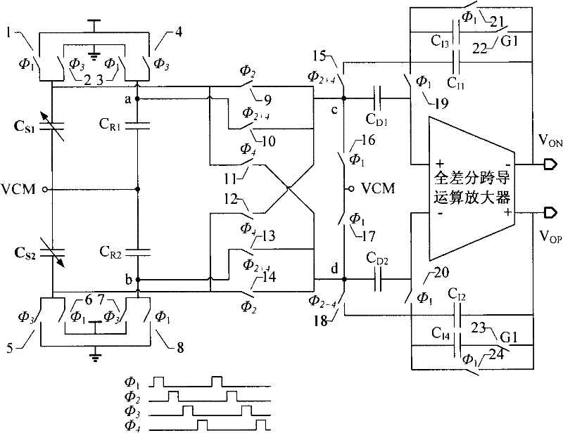
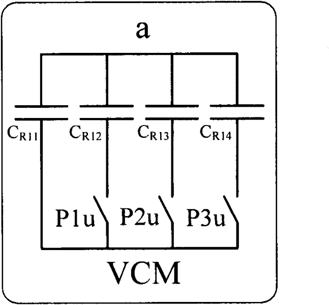
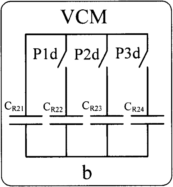
[0040]The present invention is oriented to capacitance sensors with differential structures such as micro-gyroscopes and micro-accelerometers. Aiming at the characteristics of weak output signals of micro-sensors, a fully differential weak capacitance readout circuit with cross sampling charge secondary summation is proposed. The circuit adopts switch Capacitive circuit implementation, insensitive to parasitic capacitance, suppressing circuit offset and low-frequency 1 / f noise through related double-sampling capacitors to improve capacitance resolution; using reference capacitors to reduce sensor capacitance mismatch and improve system dynamics range; fixed common-mode voltage, eliminates the impact of the mismatch of the reference capacitor in the readout circuit by means of the second summation of charges, and fixes the reference capacitor array (C R1 =C R2 ), which can eliminate the impact of common-mode voltage drift.

[0041] The cross-sampling charge quadratic summation...


PUM


Abstract

A capacitance readout circuit for secondary summation of cross-sampling charge, which is a symmetrical circuit structure, including switches 1, 2, 5, 6 for charging the sensor capacitance, reference capacitor arrays CR1 and CR2, and for charging the reference Switches 3, 4, 7, 8 for charging the capacitor array, switches 9, 10, 11, 12, 13, 14, 15, 18 for charge transfer, capacitors CD1 and CD2 for offset cancellation and low frequency noise suppression, and The switches 16 and 17 that provide the DC operating point for the circuit, the fully differential transconductance operational amplifier, the integrating capacitors CI1 and CI2 for storing the transferred charges, the integrating capacitors CI3, CI4 and switches 22 and 23 for adjusting the circuit gain, and the For the switches 19, 20, 21, 24 that provide DC bias for the fully differential transconductance inputs, the entire readout circuit is controlled by a 4-phase non-overlapping clock circuit.

Description

technical field [0001] The present invention relates to a capacitance readout circuit, and in more detail relates to a readout circuit of a high-precision capacitive micro-electromechanical sensor, such as a micro-gyroscope and a micro-accelerometer. Background technique [0002] Capacitive sensors are widely used sensors, such as capacitive pressure sensors, accelerometers, and gyroscopes. Most capacitive sensors have a differential structure, so they can usually be equivalent to a pair of differential variable capacitors, and the change in capacitance directly reflects the size of the external physical quantity to be measured. Gyroscopes and accelerometers are widely used inertial sensors to detect the angular velocity and acceleration of moving objects. They are widely used in defense technology, aerospace, automotive electronics, industrial control and other fields. With the advancement of information technology and micro-manufacturing technology, the miniaturization, i...

Claims


Application Information

Patent Timeline
Patent Type & Authority Applications(China)
IPC IPC(8): G01C19/56G01P15/125
Inventor 吴其松杨海钢张翀尹韬
Owner INST OF ELECTRONICS CHINESE ACAD OF SCI
Why Eureka
Try Eureka