A self-excited push-pull converter

A self-excited push-pull, converter technology, applied in the direction of conversion of DC power input to DC power output, AC power input to DC power output, output power conversion device, etc., can solve the problem of poor short-circuit protection performance, efficiency and efficiency. The short-circuit protection performance is not well balanced, and the short-circuit time is long, so as to achieve high-efficiency short-circuit protection performance, good short-circuit protection performance, and short-circuit protection performance improvement.

Active Publication Date: 2011-12-28
MORNSUN GUANGZHOU SCI & TECH
View PDF2 Cites 28 Cited by
  • Summary
  • Abstract
  • Description
  • Claims
  • Application Information

AI Technical Summary

Problems solved by technology

[0012] 2. The efficiency and short-circuit protection performance of the existing Royer self-excited push-pull converter are not well balanced
That is, the efficiency and short-circuit protection performance of the existing Royer self-excited push-pull converter are contradictory. During the design, it often occurs that: the short-circuit protection performance is good, and the conversion efficiency is low; poor protection
[0014] 3. For the Royer self-excited push-pull converter circuit (such as image 3 ), the existing technology cannot achieve a

Method used


Image

  • A self-excited push-pull converter
  • A self-excited push-pull converter
  • A self-excited push-pull converter

Examples


Embodiment Construction

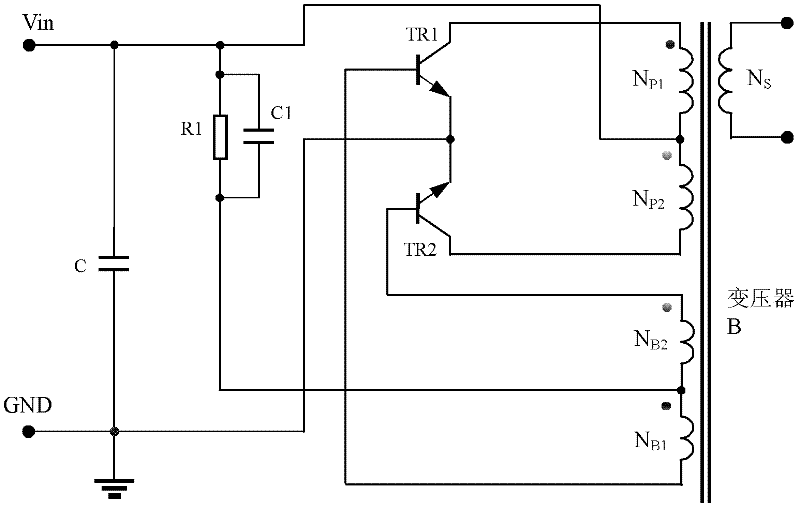
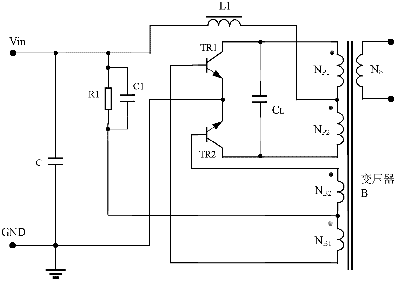
[0045] Image 6 It shows the self-excited push-pull converter of Embodiment 1 of the present invention, including filter capacitor C, bias resistor R1, starting capacitor C1, first triode TR1, second triode TR2, transformer B and inductor L N , its circuit structure is the same as that of the self-excited push-pull converter (such as figure 1 ) are basically the same, the only difference is that the power supply terminal Vin passes through the newly added inductance L N connected to the center tap of the transformer B primary winding, the inductance L N The inductance is less than one-tenth of the inductance of one of the primary windings (NP1, NP2) in transformer B, and the center tap of the primary winding is the connection point between the first primary winding NP1 and the second primary winding NP2.

[0046] Among them, when the values ​​of the two primary windings (the first primary winding NP1 and the second primary winding NP2) of the transformer B are different, the...


PUM


Abstract

The invention discloses a self-excited push-pull type converter which comprises a Royer circuit. An inductor connects a power supply terminal of the Royer circuit with a center tap of a transformer primary winding in the Royer circuit. An inductance value of the inductor is less than one-tenth of an inductance value of a primary winding in the transformer. The center tap of the primary winding isa connection point of two primary windings of the transformer. The self-excited push-pull type converter of the present invention has the characteristics of high consistency, easy debugging, low technology requirement, and good short circuit protection performance.

Description

technical field [0001] The invention relates to a self-excited push-pull converter, in particular to a self-excited push-pull converter in DC-DC or DC-AC in industrial control and lighting industries. Background technique [0002] The existing self-excited push-pull converter, the circuit structure comes from the self-excited oscillation push-pull triode single-transformer DC converter invented by G.H.Royer in 1955, which is also the beginning of realizing high-frequency conversion control circuit; some circuits From the self-excited push-pull double-transformer circuit invented by Jen Sen in the United States in 1957, it was later called the self-oscillating Jensen circuit; these two circuits are collectively referred to as the self-excited push-pull circuit pull converter. Compared with the self-oscillating Jensen circuit, the Royer circuit has an advantage. When the output load of the Royer circuit is short-circuited, the circuit design can realize the short-circuit prot...

Claims


Application Information

Patent Timeline
IPC IPC(8): H02M1/32H02M7/519H02M7/516
CPCH02M7/53835H02M3/337H02M7/538H02M3/3384H02M3/01
Inventor 王保均谢德刘伟
Owner MORNSUN GUANGZHOU SCI & TECH
Why Eureka
Try Eureka