Post Compensation Method for Transmission Time Delay in Optical Fiber Time Transfer

A technology of time transfer and compensation method, which is applied in the direction of optical fiber transmission, transmission system, optical fiber radio, etc., can solve the problems of cumbersome and troublesome operation, and achieve the effect of convenient cascading, simple method and easy operation

Inactive Publication Date: 2011-12-28
NAT TIME SERVICE CENT CHINESE ACAD OF SCI
View PDF1 Cites 30 Cited by
  • Summary
  • Abstract
  • Description
  • Claims
  • Application Information

AI Technical Summary

Problems solved by technology

In this way, it is trouble

Method used


Image

  • Post Compensation Method for Transmission Time Delay in Optical Fiber Time Transfer
  • Post Compensation Method for Transmission Time Delay in Optical Fiber Time Transfer
  • Post Compensation Method for Transmission Time Delay in Optical Fiber Time Transfer

Examples


Embodiment 1

[0022] Taking the reference time signal of 9 hours, 35 minutes, and 47 seconds from an atomic clock as an example, the post-compensation method for the transmission time delay of optical fiber time transfer is illustrated as follows.

[0023] 1. Measure fiber optic time transfer closed-loop transmission delay ΔT

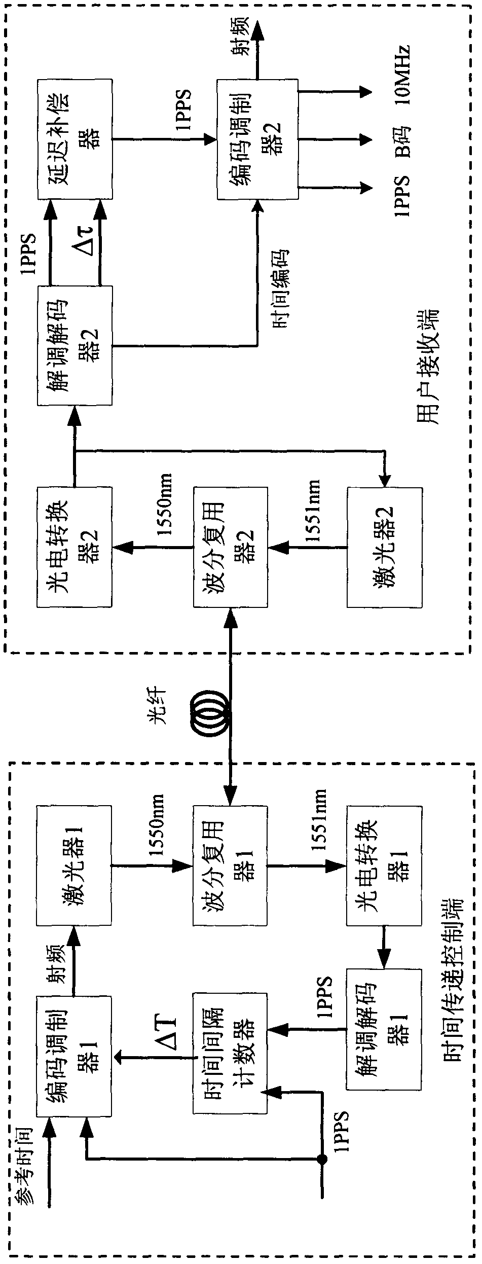
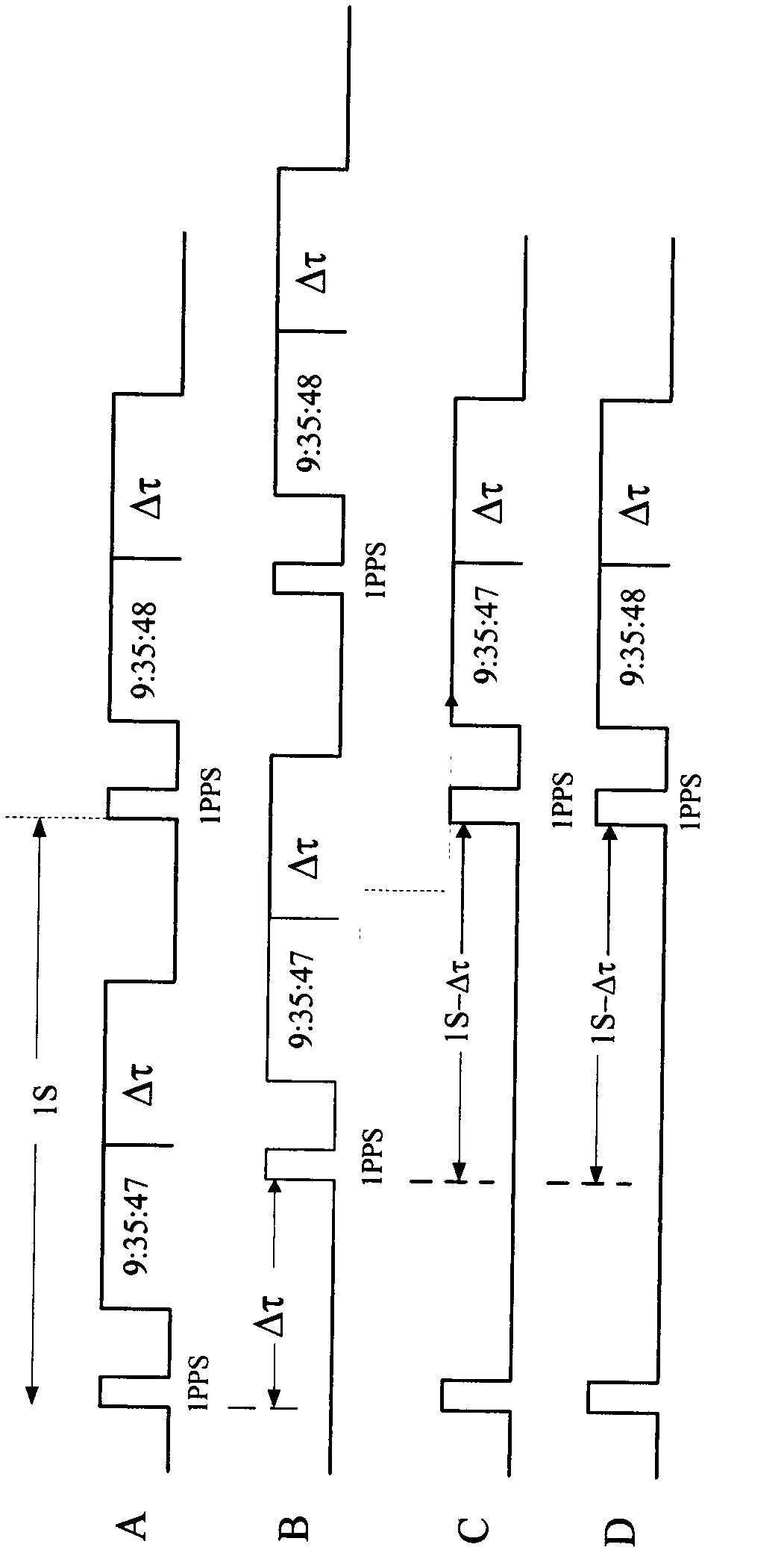
[0024] see figure 1 , 2 ,exist figure 2 Among them, sequence A is the time code signal of the time sending control terminal, including 1pps signal, time information signal hour, minute, second, and transmission time delay data Δτ; sequence B is the time code signal received by the user receiving end without time delay compensation; Timing C is the time-coded signal received by the user receiving end using the pre-compensation method; timing D is the re-encoded time-coding signal output by the user receiving end after post-compensation.

[0025] At the time transfer control end, the reference time of 9 hours, 35 minutes and 47 seconds from the atomic clock is sent...

Embodiment 2

[0035] Taking the reference time signal of 9 hours, 35 minutes, and 47 seconds from an atomic clock as an example, the post-compensation method for the transmission time delay of optical fiber time transfer is illustrated as follows.

[0036] In step 1 of measuring the closed-loop transmission delay ΔT of optical fiber time transfer, at the time transfer control end, the reference time of 9 hours, 35 minutes and 47 seconds from the atomic clock is sent to the encoder modulator 1, and the encoder modulator 1 performs time encoding according to the timing sequence A , modulated into a radio frequency signal output, the radio frequency signal is sent to the laser 1 and modulated into an optical signal with a wavelength λ1 of 1570nm, and the optical signal with a wavelength λ1 of 1570nm is fed to the wavelength division multiplexer 1, and the wavelength division multiplexer 1 converts the wavelength λ1 to 1570nm The optical signal is fed into the optical fiber and transmitted to th...

Embodiment 3

[0039] Taking the reference time signal of 9 hours, 35 minutes, and 47 seconds from an atomic clock as an example, the post-compensation method for the transmission time delay of optical fiber time transfer is illustrated as follows.

[0040] In step 1 of measuring the closed-loop transmission delay ΔT of optical fiber time transfer, at the time transfer control end, the reference time of 9 hours, 35 minutes and 47 seconds from the atomic clock is sent to the encoder modulator 1, and the encoder modulator 1 performs time encoding according to the timing sequence A , modulated into a radio frequency signal output, the radio frequency signal is sent to the laser 1 and modulated into an optical signal with a wavelength λ1 of 1590nm, and the optical signal with a wavelength λ1 of 1590nm is fed to the wavelength division multiplexer 1, and the wavelength division multiplexer 1 converts the wavelength λ1 to 1590nm The optical signal is fed into the optical fiber and transmitted to th...


PUM


Abstract

The invention relates to a post-compensation method for transmission time delay during optical fiber time transmission. The method comprises the following steps of: measuring bidirectional closed loop transmission delay deltaT during the optical fiber time transmission, calculating unidirectional transmission delay during the optical fiber time transmission, performing post-compensation on time transmission 1pps, and recoding and modulating a time signal at a user receiving end. Next-level time transmission is performed by the same method, so that cascade connection can be conveniently performed, and transmission time is remotely and accurately synchronized. Compared with the conventional pre-compensation method, the post-compensation method has the advantages that: different time information advance is not required to be set according to different levels, and pre-compensation devices of different levels are not needed, so the method is easy and convenient to operate; and the method has the advantages that the method is simple and practical, is high in reliability, and can be popularized and used in the optical fiber time transmission.

Description

technical field [0001] The invention belongs to the technical field of time-frequency transmission in electronic information science, and in particular relates to a compensation method for optical fiber time transmission transmission time delay. Background technique [0002] In the field of time-frequency transfer application in electronic information science, optical fiber time transfer adopts the transmission delay compensation method to eliminate the time delay of the transmission path and the drift caused by environmental factors, and realize high-precision time synchronization in real time. The compensation of optical fiber transmission delay is based on forming a closed-loop optical fiber time transmission path. At the time transfer sending end, the transmission delay of the closed-loop path is measured, and the delay of the round-trip transmission path is considered to be the same, so the transmission delay of the closed-loop path is taken as Half is the one-way trans...

Claims


Application Information

Patent Timeline
IPC IPC(8): H04B10/12H04L7/00H04B10/2507H04B10/2575
Inventor 张首刚梁双有陈法喜李孝峰赵侃赵文宇田晓王鑫刘涛
Owner NAT TIME SERVICE CENT CHINESE ACAD OF SCI
Why Eureka
Try Eureka