Digital large power semiconductor laser power supply
A laser power supply and semiconductor technology, applied in semiconductor lasers, lasers, laser parts and other directions, can solve the problems of unsatisfactory stability, reliability and safety, high-power semiconductor lasers are expensive, and laser service life is shortened, etc. Achieve the effect of enhancing power output capability, improving power efficiency, and high power stability
- Summary
- Abstract
- Description
- Claims
- Application Information
AI Technical Summary
Problems solved by technology
Method used
Image
Examples
Embodiment 1
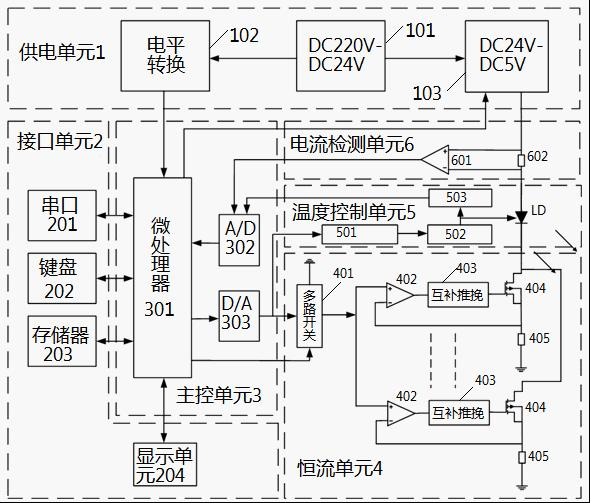
[0033] see figure 1 As shown, a digital high-power semiconductor laser power supply includes a power supply unit 1, an interface unit 2, a main control unit 3, a constant current unit 4, a temperature control unit 5 and a current detection unit 6;
[0034] The power supply unit 1 includes a 220V AC to DC 24V power supply module 101, and the 220V AC to DC 24V power supply module 101 is respectively connected to a level conversion module 102 and a DC 24V to DC 5V adjustable module 103; 220V AC to DC 24V The power supply module 101 converts AC 220V into DC 24V for direct power supply to fans, etc.; the level conversion module 102 converts DC 24V voltage into the required voltage for the main control unit 3 and interface unit 2; DC 24V to DC 5V is adjustable The module 103 provides power to the constant current unit 4, and supplies power to the laser after constant current.
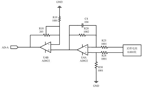
[0035] Described interface unit 2 comprises serial port 201, keyboard input 202, memory 203 and display u...
Embodiment 2
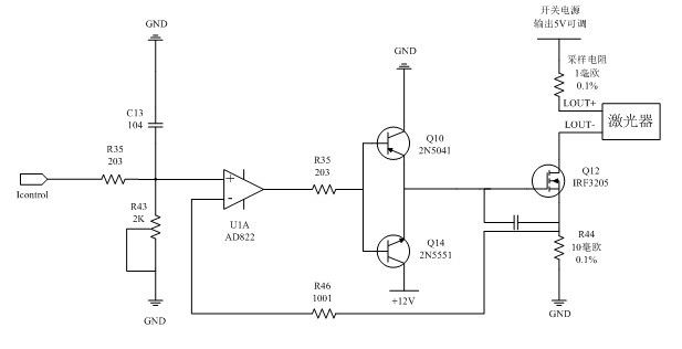
[0051] See attached figure 2 , the multi-channel switch output signal Icontrol, divided by R35 and R43, is input to the non-inverting terminal of the op amp, and the output of the op amp drives the N-channel FET Q12 to work through the complementary push-pull circuit composed of Q10 and Q14. The model of Q12 is IRF3205. Its conduction resistance is 8mΩ, the drain-source voltage can withstand 55V, and the maximum conduction current is 110A. The conduction current can be controlled by controlling the conduction status of Q12. R44 is a current sharing resistor and a sampling resistor. After feedback Resistor R46 is connected to the inverting terminal of the operational amplifier to form a negative feedback network, so that the current is balanced and stable, and the attached figure 2 Only one of the current equalizing circuits is given in this example. In this example, six circuits are connected in parallel, so that the output current is 0-60A, the ripple and noise are less tha...
Embodiment example 3
[0054] see Figure 4 As shown, in the switching power supply module circuit, two 200W VICOR modules V24B5T200BL are connected in parallel, the input voltage range is 19 V -36 V DC signal, the output voltage is 5 V adjustable DC signal, and the output power is 400W. The two modules pass The PR pins are connected in parallel, and the PC pin is the module control pin. When the PC pin voltage is lower than 2.3V, the module does not work. By adjusting R66, the output voltage of the module can be adjusted at 1.5-5V to directly provide power to the constant current unit. .
[0055] see Figure 5 As shown, POWER_ON is connected to the general-purpose IO pin of the controller. When it is at high level, transistor Q22 is turned on, optocoupler U19 and U21 are turned on, PC1 and PC2 output low level, and the module does not work. When POWER_ON is at low level Normally, the triode is off, PC1 and PC2 are in a high-impedance state, and the module works normally.
PUM
 Abstract
Description
Claims
Application Information
 - R&D
- Intellectual Property
- Life Sciences
- Materials
- Tech Scout
- Unparalleled Data Quality
- Higher Quality Content
- 60% Fewer Hallucinations
Browse by: Latest US Patents, China's latest patents, Technical Efficacy Thesaurus, Application Domain, Technology Topic, Popular Technical Reports.
© 2025 PatSnap. All rights reserved.Legal|Privacy policy|Modern Slavery Act Transparency Statement|Sitemap|About US| Contact US: help@patsnap.com


