
Device for accelerating dynamic response of control system of diesel engine

A control system and dynamic response technology, applied in engine control, electrical control, fuel injection control, etc., can solve the problem of increasing the mechanical stress load of diesel engine parts, conflicting control indicators such as overshoot and stability, and poor dynamic adjustment characteristics and other problems, to achieve the effect of speeding up dynamic adjustment and response speed, strengthening external operation capabilities, and improving dynamic adjustment characteristics

Inactive Publication Date: 2015-06-10
CHINA NORTH IND GRP NO 70 RES INST
View PDF6 Cites 0 Cited by
  • Summary
  • Abstract
  • Description
  • Claims
  • Application Information

AI Technical Summary

Problems solved by technology

[0004] (2) The classic PID control method also has certain deficiencies, such as poor environmental adaptability, control sensitivity and adjustment time, adjustment time and overshoot, overshoot and stability and other control indicators are contradictory, especially when the system working state changes suddenly When , the overshoot of the control system is large, the response time is long, and the dynamic adjustment characteristics are not good;
Under this working condition, the diesel engine control system using the classic PID control method usually has a large speed overshoot, a long stabilization time, and the diesel engine emits serious black smoke;
[0006] (4) From the perspective of the diesel engine itself, the overshoot of the speed will greatly increase the mechanical stress load of the diesel engine parts and reduce its effective fatigue life; the black smoke seriously indicates that the diesel engine's oil supply system has rough adjustment characteristics, lagging response, easy to pollute the environment, and poor combustion. Sufficient, increased fuel consumption, easy carbon deposits in the combustion chamber

Method used


Image

  • Device for accelerating dynamic response of control system of diesel engine

Examples


Embodiment Construction

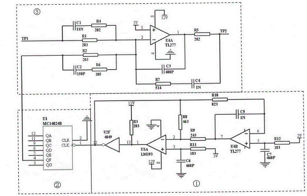
[0011] A device for accelerating the dynamic response of a diesel engine control system, which includes a comparator U3A, an operational amplifier (U4A, U4B), a logic inverter U2F, a binary counter (U1), a first resistor (R1), and a second resistor (R2) , the third resistor (R3), the fourth resistor (R4), the fifth resistor (R5), the sixth resistor (R6), the seventh resistor (R7), the eighth resistor (R8), the ninth resistor (R9), Tenth resistor (R10), eleventh resistor (R11), twelfth resistor (R12), first capacitor (C1), second capacitor (C2), third capacitor (C3), fourth capacitor (C4) , the fifth capacitor (C5), the sixth capacitor (C6), the seventh capacitor (C7) and the power supply, characterized in that the second pin of U3A is connected to the seventh pin of U4B through the ninth resistor (R9), U3A The second pin of U4B is connected to the sixth pin of U4B through the eighth resistor (R8) and the tenth resistor (R10) in series, and the 5V power supply is connected to t...


PUM


Abstract

The invention relates to a device for accelerating the dynamic response of a control system of a diesel engine, which is characterized in that a circuit of a square wave signal generator is used for providing a high frequency square wave signal with 4.7KHz of fixed frequency and 50% duty ratio so as to provide a reference frequency signal to a circuit of a frequency divider; the frequency divider is used for converting the 4.7KHz high frequency square wave signal into a 72 Hz low frequency square wave signal so as to provide a reference resonance operating frequency to an oil supply actuator of a diesel engine; after the low frequency signal is superposed with an error signal of a control loop, the gain, integration and differentiation processing are carried out so as to further increase the control accuracy, stabilize the control state and accelerate the dynamic response and regulation speed of the control system, thereby increasing the working performance of the diesel engine.

Description

technical field [0001] The invention belongs to the field of diesel engines, and in particular relates to a device for accelerating the dynamic response of a diesel engine control system. Background technique [0002] There are two main types of diesel engine control systems: analog control system and digital control system. The analog control system has been widely used because of its convenient use, good adjustability, high reliability and low price. In the field of traditional diesel engine analog control system technology, the classic PID control method is generally used. This control method has certain advantages and disadvantages, mainly in: [0003] (1) The classic PID control method has a long history, wide application, mature technology, and easy setting of control parameters, which can basically meet the general diesel engine control requirements; [0004] (2) The classic PID control method also has certain deficiencies, such as poor environmental adaptability, c...

Claims


Application Information

Patent Timeline
Patent Type & Authority Patents(China)
IPC IPC(8): F02D41/02
Inventor 杨俊恩孟长江褚全红姜承赋白思春张维彪杨国鹏
Owner CHINA NORTH IND GRP NO 70 RES INST
Learn More