Heat-pipe type boiler/furnace/kiln flue-gas waste-heat recovery device

A waste heat recovery device, heat pipe type technology, applied in indirect heat exchangers, lighting and heating equipment, etc., can solve the problems of energy waste, entering the tail of the horizontal flue, wasting fuel, etc.

Inactive Publication Date: 2012-01-18
林世鸿
View PDF3 Cites 6 Cited by
  • Summary
  • Abstract
  • Description
  • Claims
  • Application Information

AI Technical Summary

Problems solved by technology

[0003] At present, the boilers and kilns of most manufacturers use coal-fired combustion to provide heat sources, with high fuel consumption, low thermal efficiency, and backward waste discharge technology.
We know that burning coal produces a large amount of fly ash and flue gas after burning in the furnace, which enters the chimney through the flue and is discharged into the atmosphere, so that a large part of the heat is brought to the into the atmosphere, resulting in a great waste of energy
At the same time, because a large amount of fly ash and flue gas are discharged into the atmosphere from the chimney, it has caused great pollution to the surrounding environment and greatly reduced the air quality.
However, due to the tight supply in the coal market, the quality of coal used by many boilers and kilns is unstable. In order not to affect production, some enterprises have to use coal with small particle size and many powders for combustion. However

Method used


Image

  • Heat-pipe type boiler/furnace/kiln flue-gas waste-heat recovery device
  • Heat-pipe type boiler/furnace/kiln flue-gas waste-heat recovery device
  • Heat-pipe type boiler/furnace/kiln flue-gas waste-heat recovery device

Examples


Embodiment Construction

[0013] The present invention will be further described below in conjunction with the accompanying drawings and specific examples.

[0014] See figure 1 , figure 2 Shown:

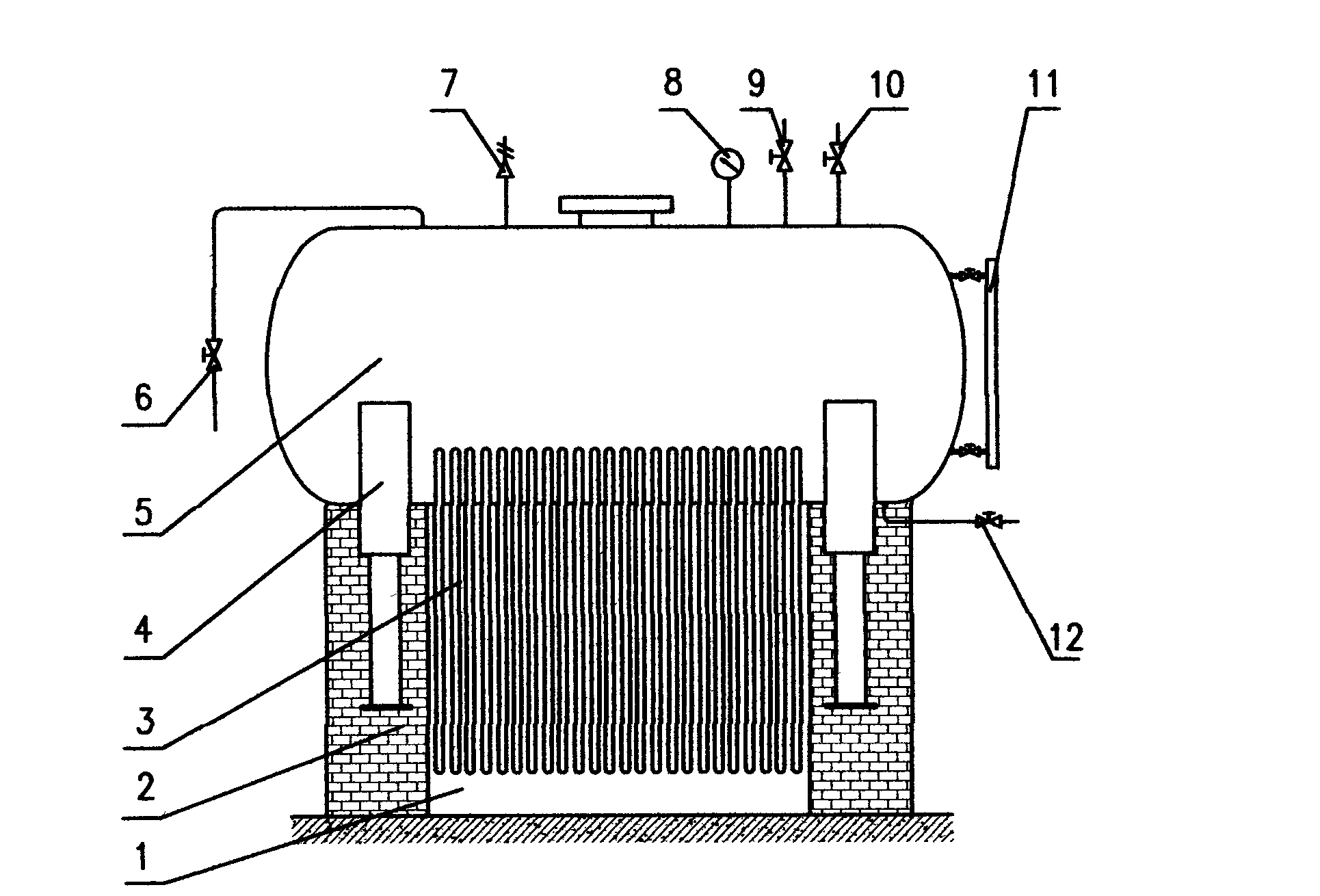
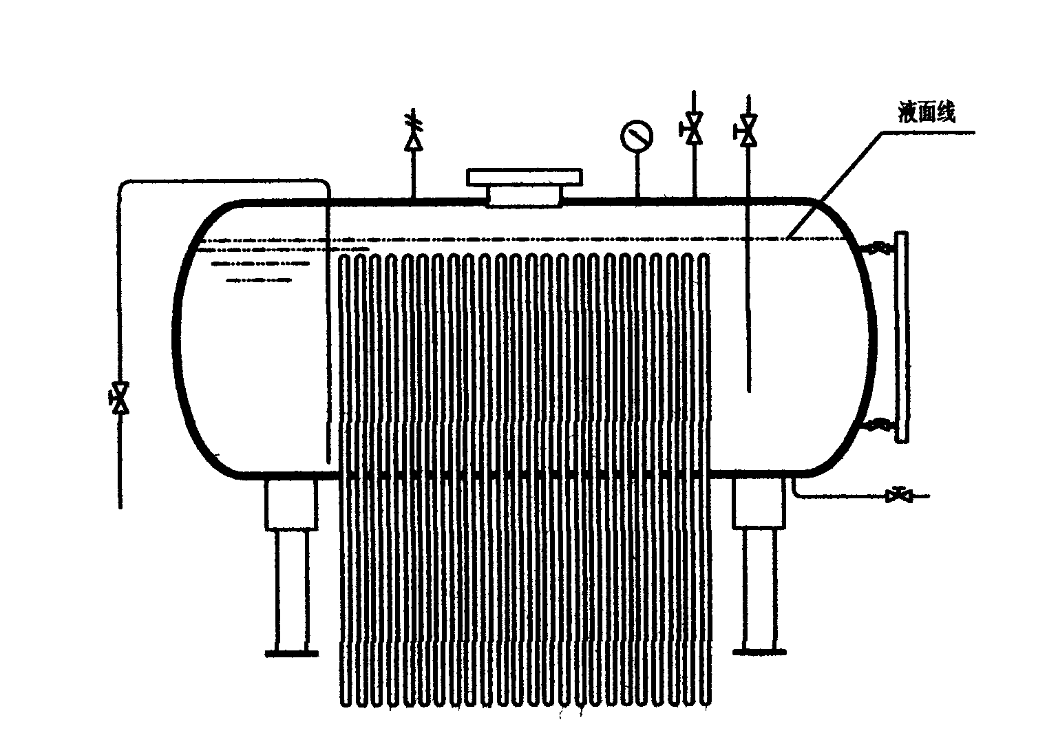
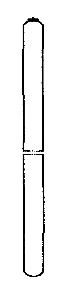
[0015] A heat pipe boiler and kiln flue exhaust waste heat recovery device whose shape is composed of a cylindrical horizontal container with a support and a heat pipe group. The recovery device includes a heat pipe group (3), a support (4), Cylindrical horizontal container (5), water inlet valve (6), safety valve (7), pressure gauge (8), discharge valve (9), water outlet valve (10), liquid level gauge (11), drain valve ( 12), wherein the legs of the support (4) of the cylindrical horizontal container (5) are embedded in the flue walls (2) on both sides of the flue (1), and the support (4) connects the cylindrical horizontal container (5) The exterior supported on the top of the flue (1), water inlet valve (6), safety valve (7), pressure gauge (8), discharge valve (9), water outlet valve (10), liquid lev...


PUM


Abstract

The invention discloses a heat-pipe type boiler/furnace/kiln flue-gas waste-heat recovery device which externally consists of a cylindrical horizontal vessel and a heat pipe set, wherein the cylindrical horizontal vessel is provided with a support, supported on the outside of the top of a flue by the support, and respectively connected with a water inlet valve, a safety valve, a pressure gauge, a discharge valve, a water outlet valve, a liquid level meter and a blow-off valve by pipes; the heat pipe set is composed of a plurality of heat pipes which are arranged according to a certain rule, the upper half parts of the pipes stretch into the water in the horizontal vessel, and the lower half parts of the pipes are inserted in the flue, so that mediums in the pipes are heated by high-temperature flue gas in the flue so as to form a steam flow, the steam flow transfers heats to the upper half parts of the heat pipes in the process of upward movement and then transfers the heats to the water in the vessel, after the heats are released, the mediums are condensed into liquid, and then the liquid flows back to the lower half parts of the heat pipes, after the process is circulated repeatedly, the heats in the flue gas are collected and rapidly transferred to the vessel so as to heat the water in the vessel to a high temperature. The waste-heat recovery device disclosed by the invention is high in heat efficiency, less in heat-transfer loss, safe and reliable.

Description

technical field [0001] The present invention relates to the field of heat energy supply, in particular to a station building that uses boilers and kilns to provide heat sources, and recycles and utilizes high-temperature waste heat in the soot exhaust gas discharged from the tail of the flue after being burned by boilers or kilns. Waste heat recovery device. Background technique [0002] Exhaustion of energy, shortage of coal burning, serious environmental pollution, energy saving, emission reduction, and environmental protection are the top priorities of the world today, because it is related to the deterioration of the human living environment and the pace of sustainable development of the world economy. The reform and opening up has enabled my country's economy to develop rapidly, so the demand for energy is also increasing. As a cheap traditional energy source, the contradiction between supply and demand of industrial raw materials is becoming more and more serious. Alth...

Claims


Application Information

Patent Timeline
IPC IPC(8): F28D15/02
CPCF28D15/0275
Inventor 林世鸿刘萍师伟卫林芝林拓
Owner 林世鸿
Why Eureka
Try Eureka