Omnidirectional cylindrical dipole antenna for underground earth-probing radars

A technology for dipole antennas and geological exploration, applied in the direction of antennas, antenna arrays, antenna supports/installation devices, etc., can solve the problems of impossibility of matching pulse radar, matching application of difficult-to-drill radar, and distortion of antenna time-domain waveforms , to achieve the effect of improving radar detection efficiency, clean radiation waveform, and obvious main-sub-ratio

Inactive Publication Date: 2013-11-06
UNIV OF ELECTRONICS SCI & TECH OF CHINA
View PDF2 Cites 3 Cited by
  • Summary
  • Abstract
  • Description
  • Claims
  • Application Information

AI Technical Summary

Problems solved by technology

The working frequency of the antenna is between 700M and 2500M, the working frequency is high and the bandwidth is only 50-60M, and the circuit is connected to the four branches correspondingly, so that the feed source and each branch can be better matched, which is helpful for the antenna Bandwidth expansion; however, the fourth branch adopts a helical structure, which increases the length of the antenna and also brings a part of the inductance effect. In addition, although the increase in the number of branches can increase the bandwidth to a certain extent, but at the same time The fluctuation (range) of S11 (antenna feed point voltage reflection coefficient) within its bandwidth is also very large, that is, the radiated energy at each frequency has a large difference, which will cause distortion of the time-domain waveform of antenna radiation, and cannot be used with pulse radar ; In addition, the antenna is an active antenna with a complex structure, and it is difficult to be used in conjunction with borehole radar

Method used


Image

  • Omnidirectional cylindrical dipole antenna for underground earth-probing radars
  • Omnidirectional cylindrical dipole antenna for underground earth-probing radars
  • Omnidirectional cylindrical dipole antenna for underground earth-probing radars

Examples


Embodiment Construction

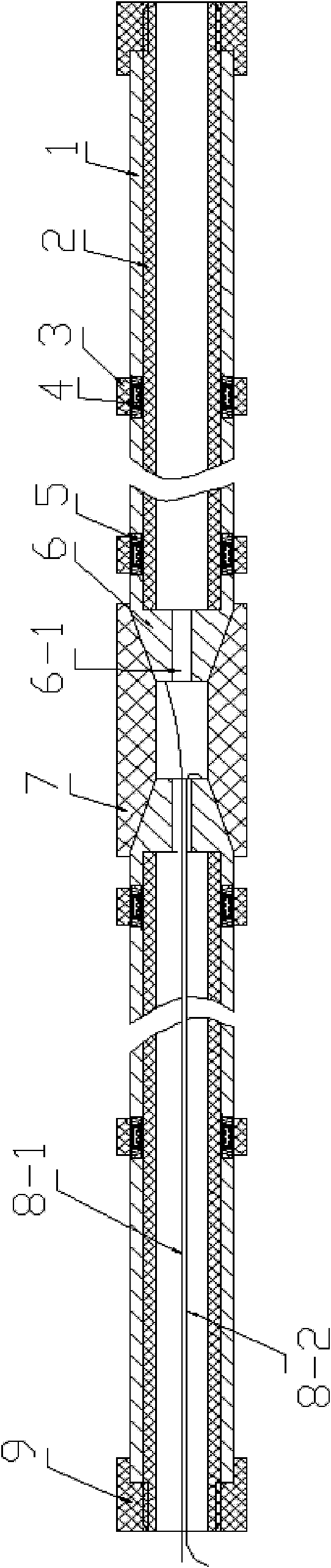
[0011] In this embodiment, the length of each (root) monopole antenna (that is, the length of half the vibrator of the antenna) is 1065mm, and the omnidirectional cylindrical dipole antenna for underground geological detection radar including 7 antenna sections 1 and one antenna head 6 is Example: The axial length of each antenna head 6 is 50mm, of which the length of the conical head is 30mm, the diameter of the upper bottom is Φ20mm, the diameter of the lower bottom is Φ40mm, the diameter of the center hole is Φ8mm, the inner and outer diameters of the rear cylindrical shape are Φ30mm and Φ40mm respectively, and the material is Stainless steel; the axial length of each tube-shaped antenna section 1 is 140 mm, the inner and outer diameters are Φ30 mm and Φ40 mm, and the material is also stainless steel; the rear end surface of the antenna head 6 and the adjacent end surfaces of each antenna section 1 are spaced at 90° Set 4 seat holes with a diameter of Φ3mm and a depth of 7.5...


PUM


Abstract

The invention belongs to an omnidirectional cylindrical dipole antenna for underground earth-probing radars, which comprises tubular monopole antenna cylinders, conical antenna heads, loading resistors, corresponding compression springs, inter-section fixing sleeves, supporting tubes, nut sleeves, connecting and fixing sleeves and coaxial cables, the loading resistors and the corresponding compression springs are respectively arranged in the holes of each two end surfaces between the antenna heads and the antenna sections and between the antenna sections, and monopole antennas are formed by the nut sleeves. Since the invention arranges the loading resistors between the antenna heads and the antenna sections and between the antenna sections to change the distribution of the current of the surface of the antenna, not only is the performance of the antenna improved, but also the production technique is simplified, the antenna can be matched with a borehole radar to operate under the conditions of center frequency equal to about 100M and bandwidth greater than or equal to 120M, the obtained waveform is neat, the main-to-side lobe ratio is distinct, tailing is tiny, and the waveform is stable; and consequently, the antenna is characterized in that: the comprehensive performance is high, the structure is simple, the diameter is small, the production cost is low, and the antenna can be matched with the borehole radar under the conditions of low frequency band and high bandwidth, and can effectively increase the performance, detection range and efficiency of the borehole radar.

Description

technical field [0001] The invention belongs to a dipole antenna used in conjunction with a detection radar, in particular to a broadband low-frequency omnidirectional cylindrical dipole antenna used in geological drilling wells in conjunction with a geological detection radar and loaded with resistance; the antenna can be used through Geological drilling wells work deep underground, and are used in conjunction with geological detection radar for geological environment investigation and resource exploration. Background technique: [0002] Ground-penetrating radar is an efficient shallow geophysical detection technology. It transmits high-frequency pulsed electromagnetic waves, uses the difference in the electrical parameters of the underground medium, and analyzes and infers the structure and material of the underground medium according to the characteristics of the amplitude and phase of the echo. feature. The geophysical methods generally adopted by geological radar are c...

Claims


Application Information

Patent Timeline
Patent Type & Authority Patents(China)
IPC IPC(8): H01Q1/12H01Q1/38H01Q21/00
Inventor 赵青唐剑明刘述章马春光
Owner UNIV OF ELECTRONICS SCI & TECH OF CHINA
Why Eureka
Try Eureka