Rectenna array for microwave reception

A technology of rectenna and receiving antenna, which is applied in the direction of antenna array, antenna, radiation element structure, etc., can solve the problems of low conversion efficiency, manpower and material resources, etc., and achieve the effect of light weight, easy array formation, and convenient expansion

Inactive Publication Date: 2012-02-15
高宝强
View PDF0 Cites 18 Cited by
  • Summary
  • Abstract
  • Description
  • Claims
  • Application Information

AI Technical Summary

Problems solved by technology

[0003] The erection of traditional high-voltage transmission lines consumes manpower and material resources, especially for mountains, deserts, and isolated islands with complex geographical env

Method used


Image

  • Rectenna array for microwave reception
  • Rectenna array for microwave reception

Examples


Embodiment Construction

[0015] The invention will be further described below in conjunction with the accompanying drawings and specific embodiments.

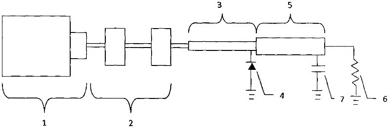
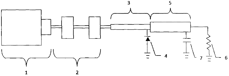
[0016] As shown in the figure, the present invention consists of the following parts: receiving antenna 1, input filter 2, matching circuit 3, rectifier diode 4, output filter 5, electrical equipment 6, and capacitor 7. The above parts are all printed circuits, and the whole is made on the PTFE double-sided copper-clad board substrate. The operating frequency of the receiving rectenna array is 2.45GHz.

[0017] The receiving antenna 1 is a linearly polarized binary series microstrip rectangular patch array, the microstrip line is fed in series, and two short stubs between the two series patches are used to adjust the direction of the antenna pattern.

[0018] The input filter 2 directly connected to the receiving antenna adopts the simplest high and low impedance structure. In order to keep the input impedance of the antenna consistent, its input and ...


PUM


Abstract

The invention provides a rectenna array for microwave reception. According to the invention, a linear polarization binary series microstrip rectangular patch array that works at a 2.45 GHz is utilized as a reception rectenna; a microstrip line series feed is employed to enable an antenna and a rectification circuit to be at a same plane; and two short branch knots that are introduced between unit patches can be used for adjusting an orientation of an antenna directional diagram. The above-mentioned structure is very convenient to be expanded and can be applied to a design of a large-scale array. According to the invention, the array has advantages of small profile, small volume and light weight; and the array has a planar structure and is easy for coplane and conformal realization with electric equipment; moreover, the reception rectenna array is wholly manufactured on a same medium substrate and is suitable for mass production with utilization of a printed circuit technology and the costs are low; and the microstrip line feeding mode enables a rectenna array to be easy to carry out array organization; therefore, the array can be applied to a large-power occasion.

Description

technical field [0001] The invention relates to a receiving conversion device in the field of wireless microwave energy transmission, that is, a planar printed rectifying antenna array, which is used for receiving and converting microwave energy into direct current. Background technique [0002] In the 1960s, in order to solve the world's growing demand for energy, the concept of space solar power plants was proposed: In space, solar cells installed on satellites are used to collect electrical energy, and then convert electrical energy into microwaves for transmission. The receiving station is responsible for receiving microwaves, which are then converted into electrical energy and input into the grid. The Japan Aerospace Development Center is also working on a similar space solar power generation system, which is expected to start before 2030. At the research base in Hokkaido, Japanese scientists used an instrument device with a diameter of 2.4 meters to conduct an experim...

Claims


Application Information

Patent Timeline
IPC IPC(8): H01Q1/38H01Q3/00H01Q13/08H01Q21/00
Inventor 高宝强李智
Owner 高宝强
Why Eureka
Try Eureka