Holographic blazed grating manufacturing method

A technology of a blazed grating and a manufacturing method, which is applied in the field of preparation of diffractive optical elements, can solve problems such as difficulty in controlling the blaze angle, and achieve the effect of realizing the blaze angle

Inactive Publication Date: 2012-02-22
SUZHOU UNIV
View PDF5 Cites 30 Cited by
  • Summary
  • Abstract
  • Description
  • Claims
  • Application Information

AI Technical Summary

Problems solved by technology

[0006] However, for the holographic ion beam etching method, since the grating blaze angle mainly depends on the three factors of the grating duty ratio, groove depth and groove shape of the photoresist mask, and the photoresist is in t

Method used


Image

  • Holographic blazed grating manufacturing method
  • Holographic blazed grating manufacturing method
  • Holographic blazed grating manufacturing method

Examples


Embodiment 1

[0058] Example 1: Please refer to Figure 5 , Figure 5 It is a schematic diagram of the effects corresponding to each step in the first embodiment of the present invention. Fabricate a holographic blazed grating with a grating period of 833nm and a blaze angle θs of 10°, which is realized by interference exposure, forward ion beam etching and oblique Ar ion beam scanning etching. The homogeneous grating produced is a rectangular grating with a width of The ratio f=a / Λ=0.5. Include the following steps:

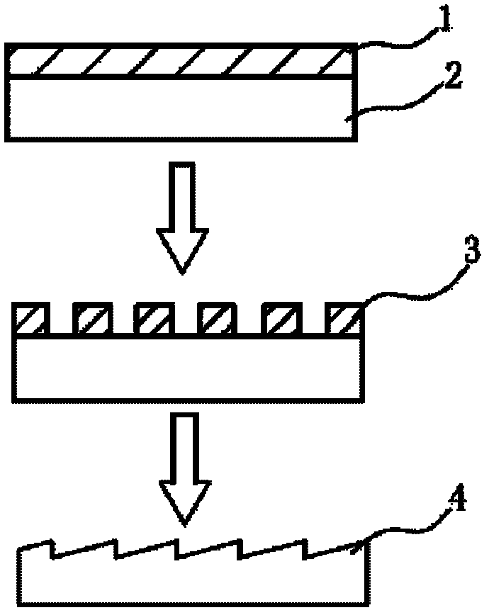
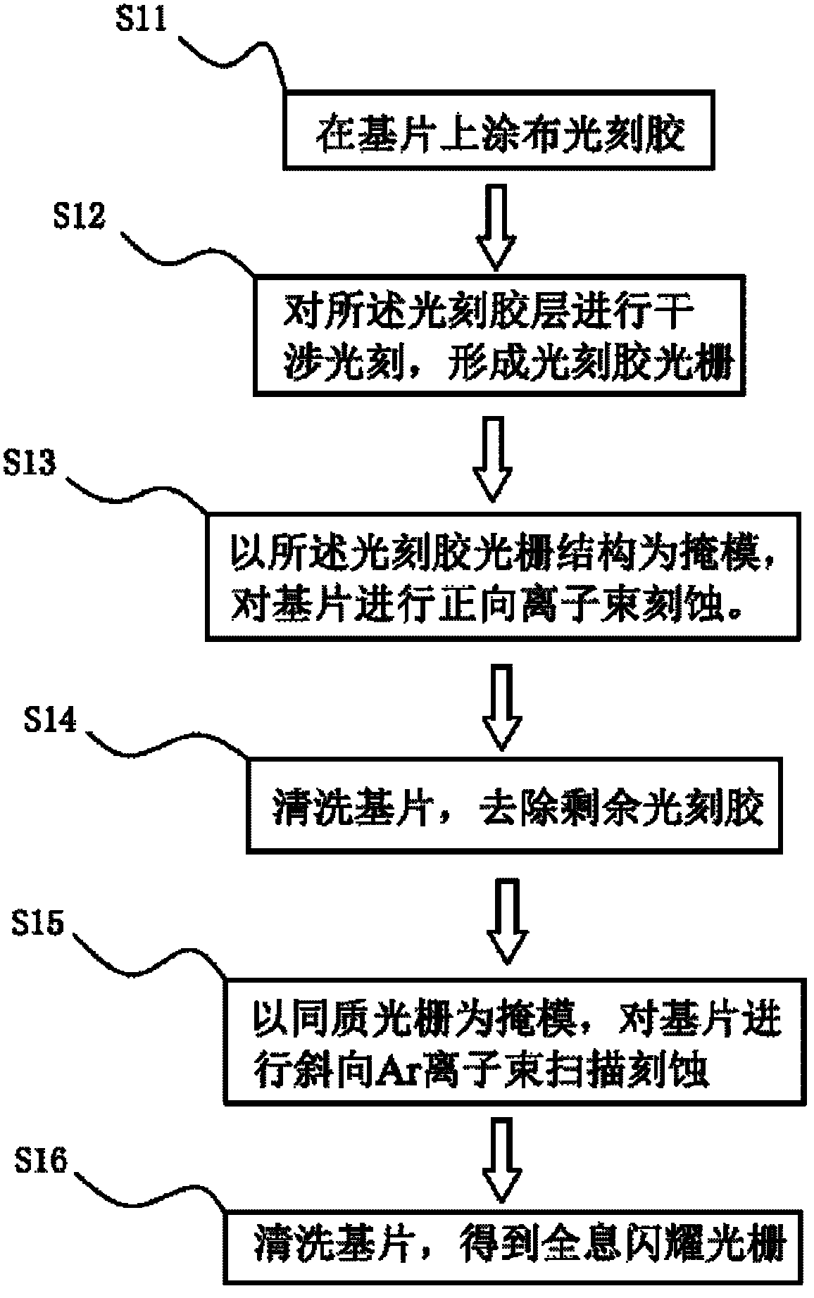
[0059] (1) Coating a photoresist 11 with a thickness of 300 nm on the quartz substrate 10 .

[0060] (2) Perform interference lithography to fabricate a photoresist grating mask 12 .

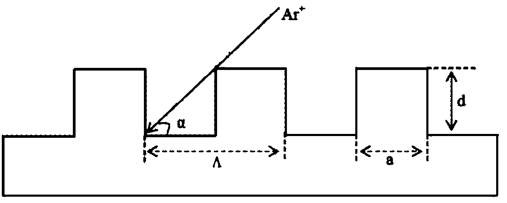
[0061] (3) Adopt rectangular grating (see image 3 ) as an example, first analyze the etching depth required to fabricate a blazed grating with a blaze angle θs of 10°. From the formula (2), the groove depth (d) of the homogeneous grating mask is 96nm. For this reason, the photoresist gra...

Embodiment 2

[0065] Example 2: Please refer to Figure 6 , Figure 6 It is a schematic diagram of the effects corresponding to each step in the second embodiment of the present invention. Fabricate a holographic blazed grating with a grating period of 833nm and a blaze angle θs of 15°, which is realized by interference exposure, forward ion beam etching, and oblique Ar ion beam scanning etching. The homogeneous grating is a rectangular grating with a width of The ratio f=a / Λ=0.35. Include the following steps:

[0066] (1) Coating a photoresist 21 with a thickness of 500 nm on the quartz substrate 20 .

[0067] (2) Perform interference lithography to fabricate a photoresist grating 22 .

[0068] (3) Perform an ashing process on the photoresist grating 22, adjust the duty ratio of the photoresist grating 22, and form a new photoresist grating 22'. The photoresist grating 22' can be transferred by forward ion beam etching to form a homogeneous grating with a duty ratio of 0.35 on the sub...

Embodiment 3

[0073] Example 3: Please refer to Figure 7 , Figure 7 It is a schematic diagram of the effects corresponding to each step in the third embodiment of the present invention. The method of making a holographic blazed grating with a grating period of 500nm and a blaze angle of 20° is realized by interference exposure, forward ion beam etching and oblique Ar ion beam scanning etching. The fabricated homogeneous grating is a trapezoidal grating with a trapezoidal angle β of 80° and a duty ratio of 0.5. Include the following steps:

[0074] (1) Coating a photoresist 31 with a thickness of 300 nm on the substrate 30 .

[0075] (2) Perform interference photolithography to fabricate a photoresist grating 32 . The groove shape of the photoresist grating here is different from the reaction time of the developer solution from top to bottom during development and etching, resulting in the upper photoresist being narrower than the lower photoresist, so that the groove shape of the phot...


PUM

PropertyMeasurementUnit
Thicknessaaaaaaaaaa

Abstract

The invention provides a holographic blazed grating manufacturing method. Through making a homogeneous grating on a substrate, taking the homogeneous grating as mask, and carrying out oblique ion beam etching, a needed blazed grating is obtained. Since time of positive ion beam etching can be controlled when making the homogeneous grating, a groove depth of the homogeneous grating is accurately controlled. In addition, after obtaining a photoresist raster through interferometric lithography, ashing technology can be increased further, a duty cycle of the photoresist raster is controlled, and a duty cycle of a needed homogeneous grating is controlled. According to the manufacturing method of the present invention, multi-parameter control of blazed grating manufacture is realized, and manufacture precision is raised.

Description

technical field [0001] The invention relates to a preparation method of a diffractive optical element, in particular to a preparation method of a holographic blazed grating. Background technique [0002] Grating is a very widely used and important high-resolution dispersive optical element, which occupies a very important position in modern optical instruments. [0003] As we all know, the principal maximum direction of diffraction by a single grating is actually not only the geometrical optics propagation direction of light, but also the zero-order direction of the entire multi-slit grating. It concentrates light energy, but cannot separate various wavelengths. In practical applications, Focus on concentrating as much light energy as possible on a specific order. For this reason, it is necessary to make the diffraction grating into a groove shape determined by calculation, so that the main maximum direction of the diffraction of a single grating groove (or the direction of...

Claims


Application Information

Patent Timeline
IPC IPC(8): G02B5/18G03F7/00
CPCG02B5/1857C23C14/00C23C14/022C23C14/027C23F4/00G02B5/1861G03F7/0005G03H1/0244G03H1/182G03H2224/04G03H2260/14
Inventor 刘全吴建宏陈明辉
Owner SUZHOU UNIV
Why Eureka
Try Eureka