Method for sludge dehydration and drying

A sludge dewatering and drying technology, applied in the direction of dewatering/drying/concentrating sludge treatment, etc., can solve the problems of large energy loss, many ancillary equipment, increase costs, etc. Effect

Inactive Publication Date: 2012-03-14
SHANGHAI CENTRIFUGE INST
View PDF2 Cites 15 Cited by
  • Summary
  • Abstract
  • Description
  • Claims
  • Application Information

AI Technical Summary

Problems solved by technology

[0008] The main problem of this technical solution is that the dried sludge particles are discharged from the dryer at a temperature of 70°C through pneumatic rotation, and enter the cyclone separator together with the wet waste gas for separation, and the other part of the wet waste gas enters the cooling process. Most of the water is condensed and precipitated in the water scrubber, and the purified waste gas leaves the scrubber at a temperature of 40°C, and the amount of water consumed by washing and condensing this part of the wet waste gas in the scrubber is very huge, and the water after cooling and washing In order to meet the requirements of environmental protection, the water treatment system needs to be purified, and there are many ancillary equipment, which increases the cost; and the use of a combustion furnace to heat the air at low temperature has low efficiency and huge energy loss

Method used


Image

  • Method for sludge dehydration and drying
  • Method for sludge dehydration and drying
  • Method for sludge dehydration and drying

Examples


Embodiment Construction

[0066] The structure of the present invention will be further described in detail below in conjunction with the accompanying drawings.

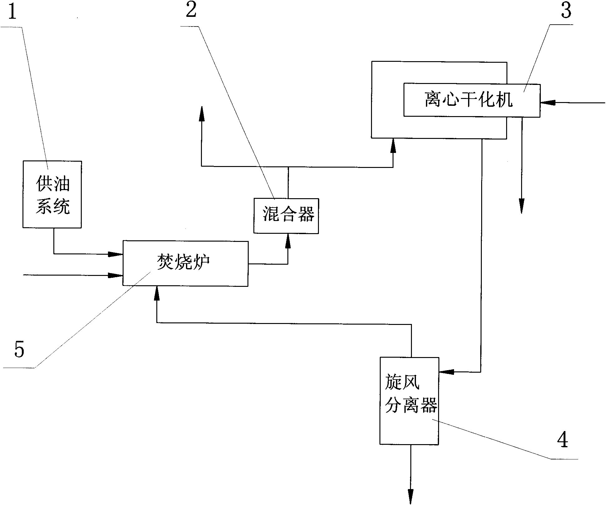
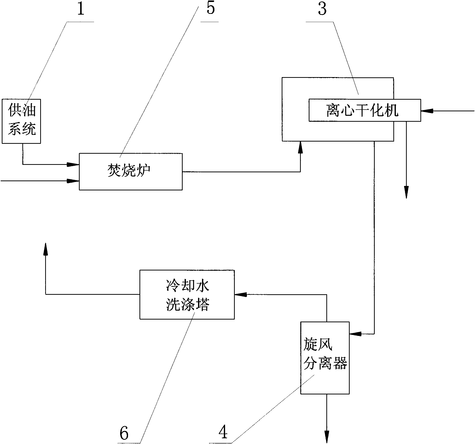
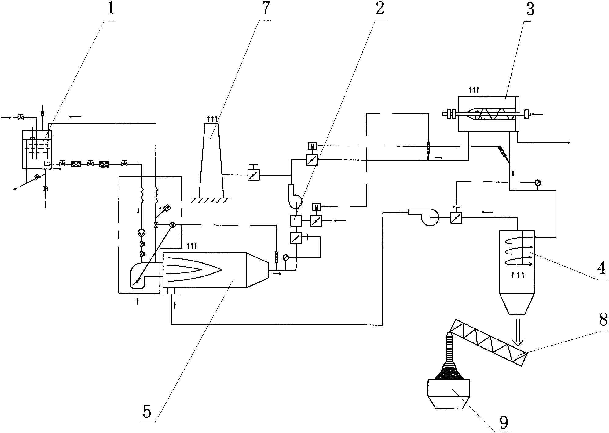
[0067] A method for sludge dehydration and drying. Sludge to be treated and dry hot gas at 280°C are sent to the centrifugal dryer 3 in two channels, and the separated clean water and gas / solid mixture are sent out from the centrifugal dryer 3 in two channels; The gas / solid mixture is sent into the cyclone separator 4 from the side, and the dry and clean solid particles are sent out from the bottom of the cyclone separator 4, and sent into the silo 9 by the screw conveyor 8; the water-containing waste gas is extracted from the top of the cyclone separator 4; The moisture exhaust gas is sent to the incinerator 5 provided by the oil supply system 1, and burns in the incinerator 5 at 900°C for 2 seconds. The high-temperature purified gas after combustion enters the high-low temperature gas mixer 2, and the purified gas at 280°C after mixing In a...


PUM

PropertyMeasurementUnit
water contentaaaaaaaaaa

Abstract

Relating to the field of sludge treatment, the invention provides a method for sludge dehydration and drying. The method comprises the steps of: sending the sludge to be treated and a hot dry gas into a centrifugal desiccation machine (3), and sending out separated clear water and a gas/liquid mixture respectively from the centrifugal desiccation machine (3); delivering the gas/liquid mixture into a cyclone separator (4), and sending out dried clean solid particles from the lower part of the cyclone separator (4); pumping out moisture-containing exhaust gas from the upper part of the cyclone separator (4); delivering the moisture-containing exhaust gas into an incinerator (5), the fuel of which is provided by an oil supply system (1), and combusting the exhaust gas in the incinerator (5) for 2sec at a temperature of 900DEG C, and sending the combusted high temperature purified gas into high-low temperature gas mixer (2) for mixing so as to obtain a purified gas of 280DEG C, providing part of the purified gas to the centrifugal desiccation machine (3) for drying, and discharging the other part of the purified gas into air through a chimney (7). In the invention, the moisture-containing exhaust gas pumped out dose not need cleaning treatment by cooling water, so that the water resource is substantially saved, and environmental protection treatment to the cooling and cleaning water is avoided. And dual application of one incinerator can improve the incinerator work efficiency. The method provided in the invention has the advantages of less equipment, simplified structure, reduced investment cost, and higher economic benefits.

Description

technical field [0001] The invention relates to the field of sludge treatment, in particular to a process for concentrating and drying sludge. Background technique [0002] In recent years, the growth trend of urban sludge output is very obvious. Sludge is a kind of porous medium with high moisture content. The moisture content of untreated sludge is as high as 95%. Because of its high water content and large volume, sludge treatment adopts different treatment methods for different purposes. [0003] The traditional sludge treatment and disposal technology system is: sludge→concentration→stabilization→dehydration. The sludge after dehydration is usually disposed of by agricultural use, landfill or incineration. [0004] In these kinds of technical systems, the agricultural use may have difficulty in transportation and large transportation due to the high moisture content of the concentrated sludge (generally 92% to 96%), or due to the difficulty in dispersing the dewatered ...

Claims


Application Information

Patent Timeline
Patent Type & Authority Applications(China)
IPC IPC(8): C02F11/14
Inventor 屈年凯顾湘刘阳
Owner SHANGHAI CENTRIFUGE INST
Why Eureka
Try Eureka