Heater structure of electronic powder firing furnace

A heater and sintering furnace technology, which is applied to electric furnace heating, lighting and heating equipment, furnaces, etc., can solve the problems of burning the heater, affecting the normal operation of the sintering furnace, and the heater failing to sinter electronic powder normally. To ensure the effect of sintering quality

Active Publication Date: 2012-03-21
SUZHOU HUIKE EQUIP CO LTD
View PDF9 Cites 2 Cited by
  • Summary
  • Abstract
  • Description
  • Claims
  • Application Information

AI Technical Summary

Problems solved by technology

However, when some new materials such as battery powder materials for new energy vehicles are sintered, the materials will volatilize a large amount of water vapor, corrosive gases and viscous organic substances when heated, and these substances tend to adhere to the On the heater, for example, water vapor causes a short circuit of the heating wire, and if the attached colloid causes local overheating and burns the heater, the heater cannot sinter the electronic powder normally, which will affect the quality of the product in the slightest, and the product will be scrapped in severe cases
In addition, the service life of the above-mentioned heating wire is short due to corrosion, and generally needs to be replaced in about a month, which not only increases the cost of use, but also affects the normal operation of the firing furnace

Method used


Image

  • Heater structure of electronic powder firing furnace
  • Heater structure of electronic powder firing furnace

Examples


Embodiment 1

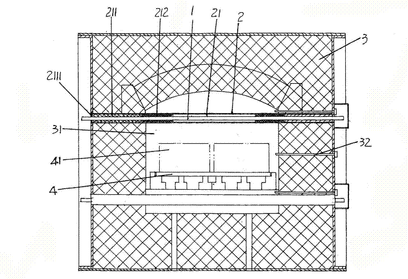
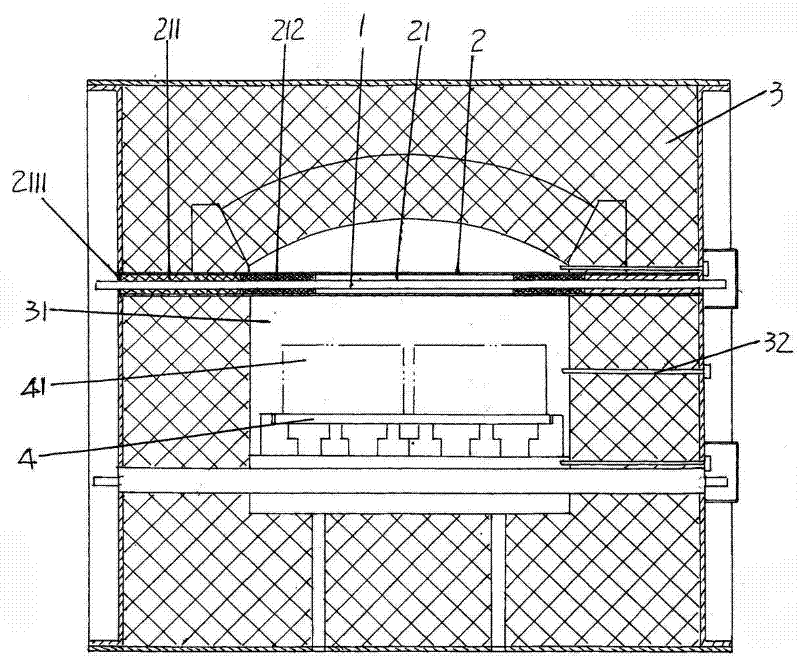
[0015] exist figure 1 In the above, the applicant shows the furnace body 3 of the electronic powder firing furnace. The furnace body 3 has a hearth 31. When in use, the electronic powder material 41 to be fired is carried on the setter 4 and the setter 4 is introduced into the furnace chamber 31, and thermocouples 32 for measuring the temperature in the furnace chamber 31 are arranged at intervals in the length direction of the furnace body 3.

[0016] The heater structure provided by the present invention is arranged at intervals along the length direction of the aforementioned furnace 31, the heater structure includes a heater body 1 and a protection tube 2, the middle part of the heater body 1 is located in the lumen 21 of the protection tube 2, and Both ends extend out of the tube cavity 21 and are fixed with the furnace body 1 shown in the figure. A first temperature-resistant spacer 211 and a second temperature-resistant spacer 212 are arranged in sequence at both ends ...

Embodiment 2

[0020] Only the heater body 1 uses a resistance wire rod, and the protective tube 2 is replaced with a quartz tube, and the rest are the same as the description of the first embodiment.

[0021] The heater structure obtained by the above-mentioned embodiments 1 and 2 has been tested by the applicant under confidentiality measures, and the results have shown that the technical effect described above by the applicant can be fully achieved, so it is an extreme technical solution.


PUM


Abstract

A heater structure of an electronic powder firing furnace belongs to the technical field of the electronic product firing furnace. The heater structure comprises a heater body and a protection tube, wherein the middle part of the heater body in the length direction is located within the cavity of the protection tube, while the two ends thereof extend out of the cavity of the protection tube; a first temperature resistant spacer bush and a second temperature resistant spacer bush are arranged at the two ends of the cavity, respectively; the end faces of the first temperature resistant spacer bush and the second temperature resistant spacer bush are in contact with each other, and both of the first temperature resistant spacer bush and the second temperature resistant spacer bush are arranged on the heater body, and wherein the first temperature resistant spacer bush extends to the cavity opening part of the cavity and is sealed by a sealing packing course. The heater structure has the following advantage that: the severe atmosphere in the hearth can be effectively prevented from affecting the heater body so that the heater body can work normally and enduringly, which is advantageous not only to ensure the sintering quality of an electronic powder material and but also to save the use cost and ensure the normal operation of the electronic powder firing furnace.

Description

technical field [0001] The invention belongs to the technical field of firing kilns for electronic products, and in particular relates to a heater structure for firing furnaces for electronic powder, which is used for heating air furnaces and atmosphere furnaces such as nitrogen furnaces and nitrogen hydrogenation furnaces. Background technique [0002] As is well known in the industry, the stability of the sintering process of electronic powder materials will directly affect the quality of electronic products, and the normal operation of the heater will have a corresponding impact on the sintering quality of electronic powder. The heaters in the prior art are all directly exposed and arranged on the top, bottom and / or left and right of the furnace, and silicon carbide rods, iron-chromium-aluminum, and chromium-nickel metal heating wires are usually used. This kind of heating wire will not produce adverse factors in the air atmosphere, that is to say, it can be used normally...

Claims


Application Information

Patent Timeline
Patent Type & Authority Applications(China)
IPC IPC(8): F27B21/08F27D11/00
Inventor 刘远
Owner SUZHOU HUIKE EQUIP CO LTD
Why Eureka
Try Eureka