
Metal surface anti-fingerprint treatment method and metal product prepared by the metal surface anti-fingerprint treatment method

A processing method and technology for metal surfaces, applied in metal material coating process, ion implantation plating, coating and other directions, can solve problems such as difficult preparation, complex composition and structure, environmental pollution, etc. fingerprint effect

Inactive Publication Date: 2012-04-04
HONG FU JIN PRECISION IND (SHENZHEN) CO LTD +1
View PDF6 Cites 14 Cited by
  • Summary
  • Abstract
  • Description
  • Claims
  • Application Information

AI Technical Summary

Problems solved by technology

However, the special organic resin composition has a complicated structure, is difficult to prepare, and is easy to cause pollution to the environment

Method used


Image

  • Metal surface anti-fingerprint treatment method and metal product prepared by the metal surface anti-fingerprint treatment method
  • Metal surface anti-fingerprint treatment method and metal product prepared by the metal surface anti-fingerprint treatment method
  • Metal surface anti-fingerprint treatment method and metal product prepared by the metal surface anti-fingerprint treatment method

Examples


Embodiment 1

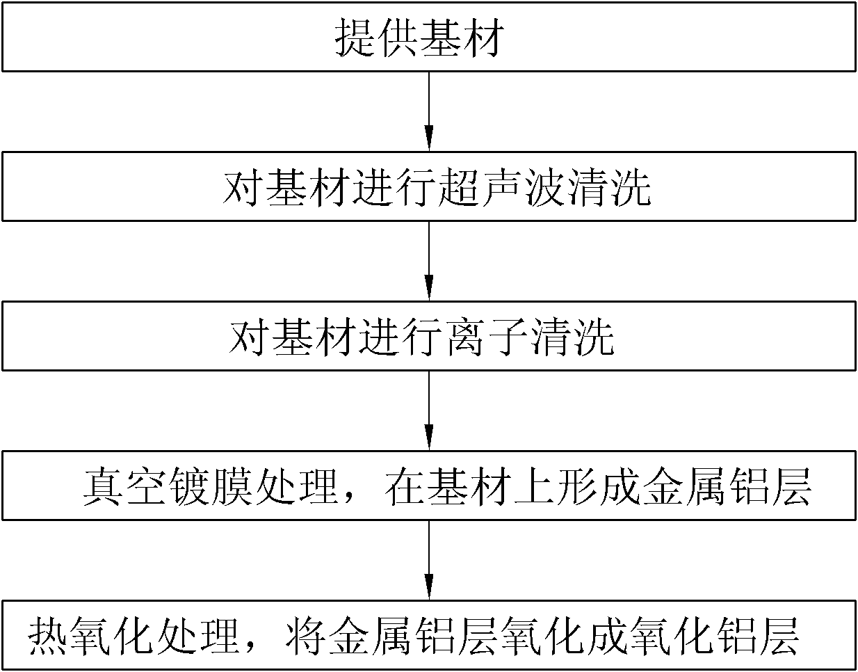
[0032] Select the stainless steel substrate, wash it in an ultrasonic cleaner filled with ethanol solution for 2 to 3 minutes, and then dry it. Put the substrate into the vacuum chamber of the DC magnetron sputtering equipment, and evacuate the vacuum chamber to 3.0×10 -3 After Pa, the flow rate was 20sccm nitrogen gas, the ion source power was turned on, the power was 1200w, and the ion source was turned off after 5 minutes of ion bombardment on the substrate.

[0033] Heat the vacuum chamber to 100°C, and feed argon gas with a flow rate of 290 sccm into the vacuum chamber, turn on the power of the pure aluminum target, the power of the target power is 3200w, adjust the bias voltage of the substrate to -120V, and deposit the metal aluminum layer . The deposition time is 10 min.

[0034] After the coating is finished, take out the substrate, put it into the oxidation furnace, and evacuate the oxidation furnace to 3.0×10 -3 Pa, set the treatment temperature at 350°C, and the...

Embodiment 2

[0037] Select the stainless steel substrate, wash it in an ultrasonic cleaner filled with ethanol solution for 2 to 3 minutes, and then dry it. Put the substrate into the vacuum chamber of the DC magnetron sputtering equipment, and evacuate the vacuum chamber to 3.0×10 -3 After Pa, the flow rate was 20sccm nitrogen gas, the ion source power was turned on, and the power was 900w, and the ion source was turned off after 8 minutes of ion bombardment on the substrate.

[0038] Heat the vacuum chamber to 120°C, and feed argon gas with a flow rate of 315 sccm into the vacuum chamber, turn on the power of the pure aluminum target, the power of the target power is 3900w, adjust the bias voltage of the substrate to -150V, and deposit the metal aluminum layer . The deposition time is 6 min.

[0039] After the coating is finished, take out the substrate, put it into the oxidation furnace, and evacuate the oxidation furnace to 3.0×10 -3 Pa, set the treatment temperature at 300°C, and t...


PUM

PropertyMeasurementUnit
thicknessaaaaaaaaaa

Abstract

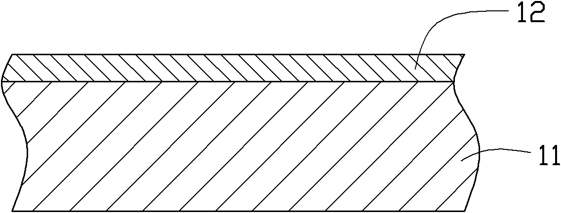
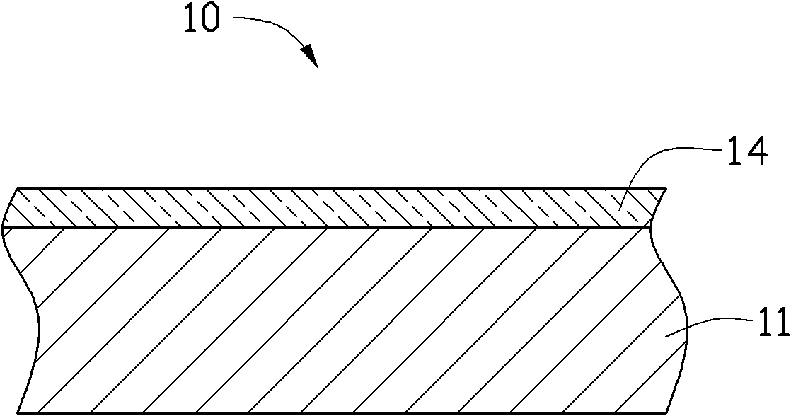
The invention provides a metal surface anti-fingerprint treatment method. The metal surface anti-fingerprint treatment method comprises the following steps of preparing a metal base material, depositing an aluminum layer on the metal base material through a vacuum coating method, and carrying out thermal oxidation treatment on the aluminum layer to enable the aluminum layer to be oxidized into an alumina layer, wherein multiple nanometer mastoids are distributed on the alumina layer. The invention also provides a metal product prepared by the metal surface anti-fingerprint treatment method. The metal product comprises a metal base material and an alumina (Al2O3) layer formed on the metal base material, wherein multiple nanometer mastoids are distributed on the surface of the alumina (Al2O3) layer.

Description

technical field [0001] The invention relates to a metal surface anti-fingerprint treatment method and a prepared metal product. Background technique [0002] As 3C electronic products are used more and more frequently, consumers have higher and higher requirements for the appearance of products. In addition to the requirements of beautiful color and comfortable handle of the product shell, the surface is also required to have good wear resistance, scratch resistance, and anti-fingerprint (anti-fingerprint) performance. [0003] In order to improve the anti-fingerprint performance of the metal surface, US Patent No. 006736908 discloses an anti-fingerprint metal surface treatment liquid. The surface treatment solution contains special organic resin, soluble vanadium compound, and soluble metal compound, which contains at least one metal element among Zn, Ti, Mo, W, Mn and Ce. The metal surface treated by this treatment solution has good resistance Fingerprinting. However, t...

Claims


Application Information

Patent Timeline
Patent Type & Authority Applications(China)
IPC IPC(8): C23C14/16C23C14/34C23C14/58C23C8/12
Inventor 张新倍陈文荣蒋焕梧陈正士彭立全
Owner HONG FU JIN PRECISION IND (SHENZHEN) CO LTD
Learn More