High rate lithium iron phosphate cell and preparation method thereof

A lithium iron phosphate battery and lithium iron phosphate technology, applied in the manufacture of electrolyte batteries, battery electrodes, secondary batteries, etc., can solve the problems of poor high-rate discharge and poor safety, and achieve improved consistency, improved safety, and improved The effect of uniformity

Active Publication Date: 2012-04-04
SHANDONG GOLDENCELL ELECTRONICS TECH
View PDF5 Cites 28 Cited by
  • Summary
  • Abstract
  • Description
  • Claims
  • Application Information

AI Technical Summary

Problems solved by technology

[0004] The purpose of the present invention is to provide a high-rate lithium iron phosphate battery and its preparation method, solve the pro...

Method used


Image

  • High rate lithium iron phosphate cell and preparation method thereof
  • High rate lithium iron phosphate cell and preparation method thereof
  • High rate lithium iron phosphate cell and preparation method thereof

Examples


Embodiment 1

[0043] Preparation of positive electrode: the active material has a specific surface area of ​​25m 2 / g lithium iron phosphate, the conductive agent is conductive carbon black Super-P, KS-6 is conductive graphite, the binder is polyvinylidene fluoride PVDF5130, nitrogen methylpyrrolidine (NMP) is the solvent, and the viscosity of the positive electrode slurry is controlled It is 3000~15000mPas. The percentages of various substances in the slurry are: LiFePO 4 :Super-P:KS-6:PVDF5130:NMP=89:4:2:5:115. First, dissolve PVDF5130 in NMP, then add the pre-mixed lithium iron phosphate, conductive graphite and conductive carbon black, and mechanically stir at high speed for 3 hours for pre-dispersion (1800r / min), and then use mechanical high-speed stirring (1500r / min) Combined with ultrasonic stirring (pressure 10MPa, ultrasonic frequency 20KHz) for 3 hours, the slurry is vacuum defoamed and then coated, using aluminum foil with a thickness of 20μm, after drying, rolling, and slittin...

Embodiment 2

[0048] Prepare the positive electrode: the active material has a specific surface area of ​​24m 2 / g lithium iron phosphate, the conductive agent is conductive carbon black Super-P, KS-6L is conductive graphite, the binder is polyvinylidene fluoride PVDF761A, nitrogen methylpyrrolidine (NMP) is the solvent, and the viscosity of the positive electrode slurry is controlled It is 3000~15000mPas. The percentages of various substances in the slurry are: LiFePO 4 :Super-P:KS-6:PVDF5130:NMP=88:4:2:6:115. First, dissolve PVDF761A in NMP, then add the pre-mixed lithium iron phosphate, conductive graphite and conductive carbon black, and mechanically stir at high speed for 3 hours for pre-dispersion (1800r / min), and then use mechanical high-speed stirring (1600r / min) Combined with ultrasonic stirring (pressure 11MPa, ultrasonic frequency 20KHz) for 2.5 hours, the slurry is vacuum defoamed and then coated, using aluminum foil with a thickness of 20μm, after drying, rolling, and slittin...


PUM

PropertyMeasurementUnit
Thicknessaaaaaaaaaa
Thicknessaaaaaaaaaa
Widthaaaaaaaaaa

Abstract

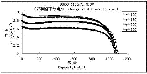
The invention discloses a high rate lithium iron phosphate cell and a preparation method thereof. The method comprises steps of preparation of an anode slurry and a cathode slurry, design of an anode sheet and a cathode sheet and design of cell safety, and aims to improve rate performance of a lithium iron phosphate cell and enhance cell safety. The preparation of the anode slurry and the cathode slurry employs a method combining ultrasonic mixing and mechanical stirring to enhance slurry disperse effect. The anode is prepared by pulping a lithium iron phosphate active material, a conductive agent and a binder according to a certain ratio and coating on an aluminium foil. The cathode is prepared by pulping graphite (or intermediate phase carbon microballoon), a conductive agent and butadiene styrene rubber (SBR) according to a certain ratio and coating on a copper foil. The anode and the cathode are prepared into a cylinder cell; an electrical core is assembled under an atmosphere protection environment; and a cap deflation apparatus is used to enhance safety of the cell. The lithium ion cell of the invention has good safety and can realize high rate 30 C continuous discharge.

Description

technical field [0001] The invention belongs to the technical field of lithium ion batteries, in particular to a high-rate lithium iron phosphate battery and a preparation method thereof. Background technique [0002] The development of new materials and the development of renewable energy technologies have become one of the major issues to be solved by mankind in the 21st century. The chemical power source as an energy storage and conversion device is an important means to effectively utilize energy. At present, lithium-ion batteries and fuel cells are research hotspots in the field of chemical power sources, especially as power batteries, which are of great significance to environmental protection and social development. Lithium-ion batteries have attracted widespread attention from all over the world due to their high operating voltage, high energy density, low self-discharge rate, and environmental friendliness. [0003] At present, lithium cobalt oxide batteries, ...

Claims


Application Information

Patent Timeline
IPC IPC(8): H01M10/0525H01M4/62H01M4/58H01M10/058
CPCY02E60/122Y02E60/10Y02P70/50
Inventor 李涛关成善宗继月
Owner SHANDONG GOLDENCELL ELECTRONICS TECH
Why Eureka
Try Eureka