Exciting current given device of induction motor of electric vehicle

A technology of excitation current and induction motor, which is applied in the direction of motor generator control, electromechanical transmission control, electronic commutation motor control, etc., and can solve problems such as PI output limitation

Inactive Publication Date: 2012-04-04
UNIV OF ELECTRONICS SCI & TECH OF CHINA
View PDF6 Cites 28 Cited by
  • Summary
  • Abstract
  • Description
  • Claims
  • Application Information

AI Technical Summary

Problems solved by technology

This scheme has strong robustness, but currently the output of the voltage closed-loop PI does not use the

Method used


Image

  • Exciting current given device of induction motor of electric vehicle
  • Exciting current given device of induction motor of electric vehicle
  • Exciting current given device of induction motor of electric vehicle

Examples


Embodiment

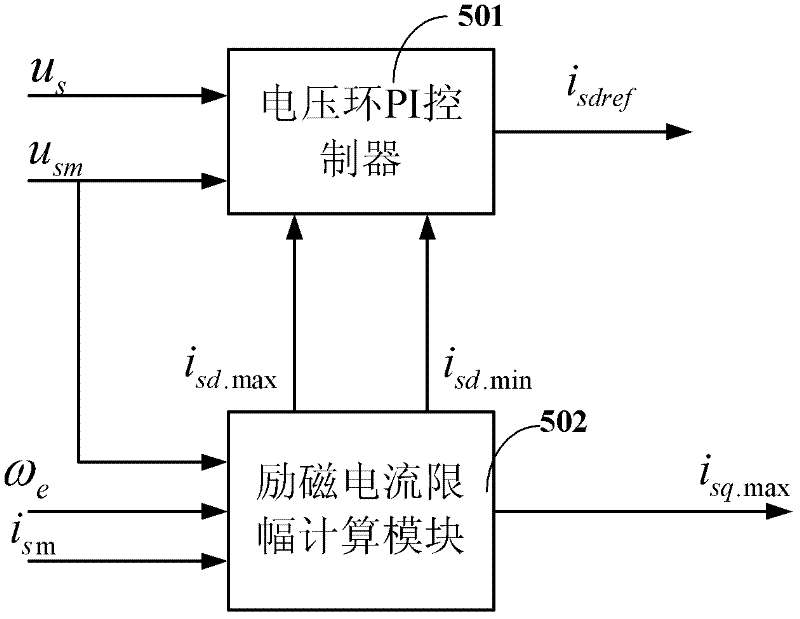
[0033] figure 1 It is a principle block diagram of a specific embodiment of the excitation current setting device for an electric vehicle induction motor of the present invention.

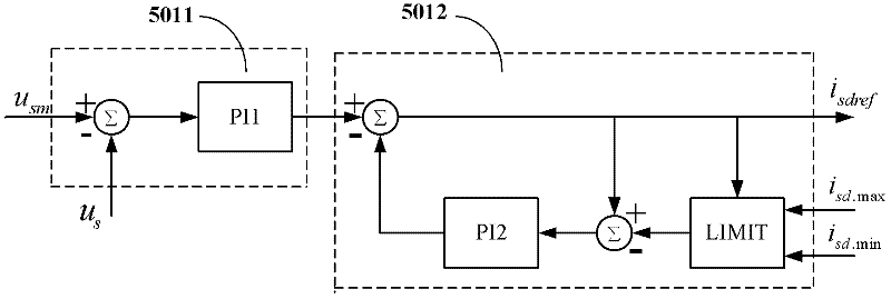
[0034] In this example, if figure 1 As shown, the excitation current setting device of the electric vehicle induction motor of the present invention includes two parts: a voltage loop PI controller 501 and an excitation current limiting calculation module 502 .

[0035] Excitation current limit calculation module 502 according to the input actual synchronous speed ω e , The maximum safe operating current of the induction motor i sm and the maximum voltage vector u sm According to the formulas ①~③, the maximum value i of the excitation current limit is calculated according to the constant torque area, constant power area and constant voltage area respectively sd.max and minimum i sd.min , and then the maximum value i of the excitation current limit calculated by formula ② and formula ③ sd.max ...

example

[0049] Apply the excitation current setting device of the electric vehicle induction motor of the present invention to an electric vehicle whose body weight is 1419kg, the peak power of the battery pack is 25KW, and the peak power of the induction motor is 75KW for real-time simulation. In the example, the initial value of the battery SOC is 0.7, the set working threshold is 0.4, and the battery discharge SOC limit is 0.15.

[0050] Figure 4 It is the boost curve of the vehicle speed before and after the electric vehicle induction motor excitation current setting device of the present invention is applied to the electric vehicle.

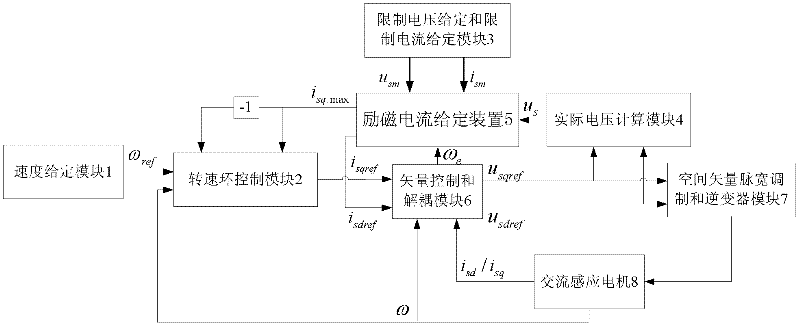
[0051] When the present invention is not used, the excitation current i sdref The value of the rated value i sdn , torque command current i sqref It is given by the speed loop control module 2. When using the present invention, the excitation current i sdref Given by the excitation current setting device 5, the torque command current i sqref ...


PUM


Abstract

The invention discloses an exciting current given device for an induction motor of an electric vehicle. On the basis of the prior art, the exciting current given device is additionally provided with an exciting current limiting calculation module and a limiting PI (proportional integral) control module. When the induction motor normally runs, the calculated amplitude limiting maximum value (isd.Max) of the exciting current decreases along with the increase of the real synchronous speed omega e. The exciting current isdref of a voltage loop PI controller decreases under the condition of invariable maximum voltage vector (usm). Due to the decrease of the exciting current (isdref), the counter electromotive force of the induction machine decreases, therefore, under the condition of invariable busbar voltage uDC, the induction motor can rise to a higher rotating speed. In addition, according to the exciting current given device of the induction motor of the electric vehicle, the calculation of switching points among a constant torque area, a constant power area and a constant voltage area is eliminated, so that the level jump of output exciting currents caused by the inaccurate calculation of switching points can be effectively prevented, the given value of the exiting currents can vary stably, the joggling of the induction motor control caused by the level jump of the given valueof the exciting currents is reduced, and the safety of the induction motor control is improved.

Description

technical field [0001] The invention belongs to the technical field of electric vehicle motor control, and more specifically relates to how an electric vehicle motor drive controller sends excitation current to an induction motor setting device. Background technique [0002] With the development of society and the increasingly prominent issues of energy and environmental protection, pure electric vehicles have attracted more and more attention from all over the world due to their advantages of zero emission and low noise. Electric vehicles have become the development direction of the automobile industry in the 21st century. One of the most important development directions of vehicles. However, due to the limitation of the characteristics of the induction motor itself and the limitation of the power supply battery voltage, the electric vehicle cannot work in the constant torque region when driving at high speed, but in the constant power region. At this time, it is necessary ...

Claims


Application Information

Patent Timeline
IPC IPC(8): H02P21/14H02P21/22
Inventor 郑宏徐红兵凡时财王博
Owner UNIV OF ELECTRONICS SCI & TECH OF CHINA
Why Eureka
Try Eureka