Resonance type surface acoustic wave passive wireless array sensing system and method thereof

A surface acoustic wave, passive wireless technology, applied in the direction of electrical components, impedance networks, etc., can solve the problems of large scattering loss of surface acoustic wave, poor measurement accuracy of sensors, and poor frequency selectivity

Inactive Publication Date: 2012-04-04
武汉烽火富华电气有限责任公司
View PDF4 Cites 18 Cited by
  • Summary
  • Abstract
  • Description
  • Claims
  • Application Information

AI Technical Summary

Problems solved by technology

The resonant coded SAW device solves the problem of large-scale array sensing of the resonant SAW, but compared with the resonant SAW device, the frequency selectivity of the resonant coded SAW period becomes worse, and the sensor measures The accuracy becomes worse, and the surface acoustic wave has greater scattering loss, transmission loss, and the wireless working distance becomes closer

Method used


Image

  • Resonance type surface acoustic wave passive wireless array sensing system and method thereof
  • Resonance type surface acoustic wave passive wireless array sensing system and method thereof
  • Resonance type surface acoustic wave passive wireless array sensing system and method thereof

Examples


Embodiment 1

[0045] Embodiment 1: A plurality of radio frequency coding switches discretely distributed in space control the resonant surface acoustic wave passive wireless temperature sensor to realize the temperature detection of the substation capacitor bank array.

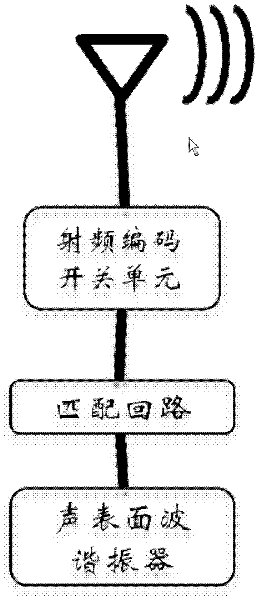
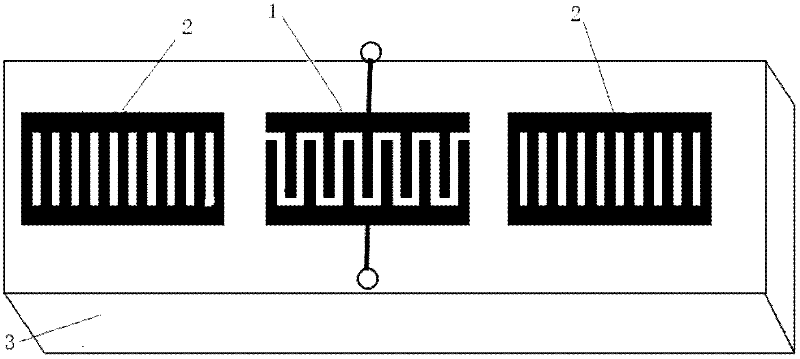
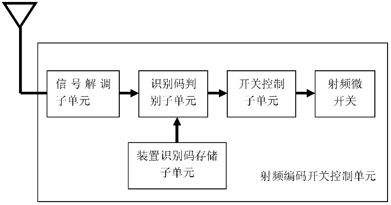
[0046] use figure 1 , figure 2 , image 3 , Figure 5 with Image 6 In the shown structure, the surface acoustic wave resonator whose resonant frequency is distributed in the amateur wireless segment of 433MHz is selected as the temperature sensitive element. The measurement temperature changes between -12 degrees Celsius and 120 degrees Celsius, which will cause the resonant frequency of the resonator to change within 1.3MHz, so the emission frequency range is 432MHz-434MHz. The antenna of the signal transmitting and receiving processing unit chooses a flat inverted F antenna, and the sensor antenna chooses a small helical antenna, and the working distance is more than 3 meters. The resonator selection uses 100 ident...

Embodiment 2

[0047] Embodiment 2: A plurality of radio frequency coding switches discretely distributed in space control the resonant surface acoustic wave passive wireless pressure sensor to monitor the tire pressure of large long-distance trucks.

[0048] The number of tires on a large long-distance truck must be more than 6, and the maximum distance between adjacent tires can exceed two meters. In order to achieve real-time monitoring of tire pressure and ensure truck driving safety, a radio frequency code switch can be installed on each tire to control resonance Type surface acoustic wave passive wireless pressure sensor, the transmitting antenna of the information transmitting unit is a flat plate antenna placed on the chassis of the truck, using figure 1 , figure 2 , image 3 , Figure 5 with Image 6 For the structure shown, the resonant frequency can be selected as 433MHz, according to Figure 7 The sensor information query logic queries the tire pressure of each tire in turn....


PUM


Abstract

The invention belongs to the technical field of surface acoustic wave sensing technology, particularly to a resonance type surface acoustic wave passive wireless array sensing system; the system comprises a signal transmitting and receiving process unit, and a plurality of sensor units arranged at the same or different space positions, wherein each sensor unit includes a resonance type surface acoustic wave sensor, a matching loop configured with each resonance type surface acoustic wave sensor cooperatively, a radio frequency coding switch unit connected with the matching loop and comprising a radio frequency coding switch, and a sensing antenna connected with the radio frequency switch unit; and the signal transmitting and receiving process unit is responsible for transmitting an intercarrier signal with certain frequency band, controlling breakover or cutoff state of the radio frequency coding switch, and detecting echo frequency characteristics of a surface acoustic wave resonator. The system not only keeps the advantage of the resonance type passive wireless sensor in far operating distance, but also overcomes and breaks through the shortage that the resonance type passive wireless sensor cannot be encoded in large scale.

Description

technical field [0001] The invention belongs to the technical field of surface acoustic wave sensing, and in particular relates to a resonant surface acoustic wave passive wireless array sensing system and a method thereof. technical background [0002] Today, with the rapid development of the Internet of Things and smart grids, sensors are widely used for real-time diagnosis and detection of sensing objects. The surface acoustic wave sensor is a new type of sensor developed since the 1980s. It can be widely used to monitor physical parameters such as temperature, pressure, stress, strain, acceleration, and flow. It can also be used in sensitive components (surface acoustic wave resonators) On the substrate, the surface acoustic wave propagation path is covered with selective chemical adsorption film and biofilm to monitor corresponding physical and chemical parameters and biological parameters. [0003] Existing passive wireless temperature measurement schemes can be divid...

Claims


Application Information

Patent Timeline
Patent Type & Authority Applications(China)
IPC IPC(8): H03H9/145
Inventor 蒋进京邹俊华余灯彭光尼胡鹏
Owner 武汉烽火富华电气有限责任公司
Why Eureka
Try Eureka