Composite phase change heat exchange system for flue gas heat recovery of boiler

The invention relates to a technology of composite phase transformation heat and waste heat recovery, which is applied to the device field in the field of boiler heat transfer technology.

Inactive Publication Date: 2012-04-11
王海波
View PDF9 Cites 10 Cited by
  • Summary
  • Abstract
  • Description
  • Claims
  • Application Information

AI Technical Summary

Problems solved by technology

[0025] The purpose of the present invention is to solve the above-mentioned problems in the prior art, eliminate the defects caused by the use of GGH, solve the difficult problem of arranging the heat exchange circular tube evaporation section in the vertical flue or inclined flue, and the evaporation of phase change heat exchangers. The difficult problem that the evaporating section and the condensing section must be arranged separately, realize the integrated and compact arrangement of the evaporating section and the condensing section of the phase change heat exchanger, realize a truly integrated composite phase change heat exchanger, and reduce the degree of harm of low-temperature corrosion. To achieve the purpose of energy saving, water saving and emission reduction

Method used


Image

  • Composite phase change heat exchange system for flue gas heat recovery of boiler
  • Composite phase change heat exchange system for flue gas heat recovery of boiler
  • Composite phase change heat exchange system for flue gas heat recovery of boiler

Examples


Embodiment 1

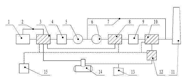
[0088] Composite phase change heat system for boiler flue gas waste heat recovery (see attached Figure 7 To attach Figure 10 and attached drawings), using air, heat transfer oil, etc. as working fluids for recycling waste heat, including boiler flue, internal and external equipment of the flue, connecting pipes, and control instrument valves. The flue is provided with a heat transfer oil heater 43, a grade I composite phase change heat exchanger 24, a grade II composite phase change heat exchanger 29, a grade III composite phase change heat exchanger 31, and the boiler's original Economizer 22, air preheater 23, dust collector 26, desulfurization tower 30, etc. Outside the flue, a Class I temperature regulation system 35, a Class II temperature regulation system 40, a Class I frequency regulation pump 33, a heat exchanger 34, a Stage II frequency regulation pump 39, and matching automatic control devices 36, heat conduction oil pumps 44, and oil-gas separators 45 , high-le...

Embodiment 2

[0114] The I, II and III composite phase change heat exchangers in the present invention can be arranged alone or in multiples, and multiple composite phase changers in each stage can be connected in series, in parallel or in combination. Multiple composite phase-change heat exchangers in stage I can be equipped with a separate temperature adjustment system; multiple composite phase-change heat exchangers in stage II can be equipped with a temperature regulation system; multiple composite phase-change heat exchangers in stage III can be set Share a Class I temperature control system or set the temperature control system separately. The heat medium circuit of multiple composite phase change heat exchangers in stage III can be provided with a series circuit of high-temperature heat transfer oil, or a series-parallel circuit of high-temperature heat transfer oil, etc. All the other implementation methods are the same as in Example 1.

[0115] For the composite phase-change heat ...


PUM


Abstract

The invention discloses a composite phase change heat exchange system for flue gas heat recovery of boiler, comprising an original coal saving device of the boiler and an air pre-heater, a dust remover and a desulfurization tower; a heat conducting oil heater, a stage I composite phase changer, a stage II composite phase changer, a stage III composite phase changer, and a temperature adjusting system matched with the stage I, state II and stage III composite phase changers are disposed in the flue; the temperature adjusting system can be used for conveniently adjusting the wall surface temperature of the phase change heat exchanger; the heat conducting oil is used as the heat source of the stage III phase change heat exchanger, so as to improve the flue purity and reach the flue discharge requirement. The invention can solve the difficult problem that it is difficult to dispose the evaporation section of the heat exchange round tube in vertical flue or oblique flue, so as to realize the integrated compact arrangements of the evaporation section and condensation section of the phase change heat exchanger; the disadvantage of GGH is overcome; the hazard degree of low-temperature corrosion is decreased, so as to realize the targets of energy saving, water saving and emission reduction.

Description

technical field [0001] The invention relates to a device in the technical field of boiler heat transfer, in particular to a composite phase-change heat system for boiler flue gas waste heat recovery. Background technique [0002] At present, more than 80% of domestic thermal power plants use gas-gas heat exchangers (GGH for short) in the wet flue gas desulfurization (Flue Gas Desulfurization, referred to as FGD). , the direct equipment cost of installing GGH is about 1.1 billion yuan. Other related costs include: increased booster fan due to the installation of GGH, increased control points of the control system, increased flue length, GGH support and corresponding building installation costs, etc., the sum of which accounts for about 15% to 20% of the total investment of FGD . The pressure drop of flue gas when GGH is installed is about 1200Pa. In order to overcome these resistances, the pressure head of the booster fan must be increased, which greatly increases the opera...

Claims


Application Information

Patent Timeline
Patent Type & Authority Applications(China)
IPC IPC(8): F23J15/00
Inventor 王海波朱利洪韩兴平王海军
Owner 王海波
Why Eureka
Try Eureka