Three-dimensional real-time super-resolution digital holographic recording method

A technology of digital holography and recording method, applied in microscopes, optics, instruments, etc., can solve the problem of not being able to have high time and high spatial resolution at the same time, achieve spatial and temporal resolution, achieve common improvement, and large field of view. and depth of field effects

Inactive Publication Date: 2012-04-11
KUNMING UNIV OF SCI & TECH
View PDF1 Cites 9 Cited by
  • Summary
  • Abstract
  • Description
  • Claims
  • Application Information

AI Technical Summary

Problems solved by technology

[0007] The purpose of the present invention is to provide a three-dimensional real-time super-resolution digital holographic recording method for the shortcomings of existing digital holographic microscopy systems that cannot simultaneously have high time, high spatial resolution, large field of view, and large depth of field. Division, time division and polarization hybrid multiplexing technology, simultaneously record four holograms containing two transient moments and high and low frequency information of each transient moment in the same frame of the digital camera, so that the digital holographic microscope system has both Features of high temporal and spatial resolution, large field of view, long working distance and large depth of field

Method used


Image

  • Three-dimensional real-time super-resolution digital holographic recording method
  • Three-dimensional real-time super-resolution digital holographic recording method
  • Three-dimensional real-time super-resolution digital holographic recording method

Examples


Embodiment 1

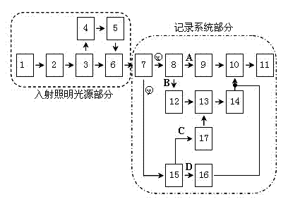
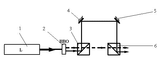
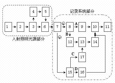
[0031] Embodiment 1: as figure 1 , 2 As shown, the three-dimensional real-time super-resolution digital holographic recording method is realized as follows: first, wavelength division, angle division, time division and polarization multiplexing technology are used, and frequency doubling crystals, dichroic mirrors, mirror combinations and non-polarization beam splitting are used mirror, which divides a femtosecond laser pulse with a central wavelength of 800nm ​​into two short pulses with different wavelengths and output time differences, and use the two as the incident light of the recording system; the central wavelength of the long-wavelength pulse is 800nm, The central wavelength of the short-wavelength pulse is 400nm, and the laser pulse with a wavelength of 400nm lags behind the laser pulse with a wavelength of 800nm ​​to reach the recording system. The optical path difference they experience is 15μm, that is, the time interval between their outputs is 50fs. Then, multi...

Embodiment 2

[0063] Embodiment 2: as figure 1 , 2 As shown, the specific process of the three-dimensional real-time super-resolution digital holographic recording method is the same as that in Embodiment 1. The central wavelengths of the two incident pulsed lasers are 1030nm and 515nm respectively, and the time interval between pulses of different wavelengths reaching the recording system is controlled to be 800fs. Two beams of light illuminate the object, one beam illuminates the measured object in a direction perpendicular to the object plane, and the other beam is inclined at 12 o Irradiate the object to be measured.

[0064] The system used in the three-dimensional real-time super-resolution digital holographic recording method is the same as that in Embodiment 1. The laser 1 used is an ORANGE-type ytterbium-doped fiber oscillator with an output laser pulse center wavelength of 1030nm and a pulse time interval of less than 100fs. The frequency doubling crystal 2 can double the frequ...

Embodiment 3

[0065] Embodiment 3: as figure 1 , 2 As shown, the specific process of the three-dimensional real-time super-resolution digital holographic recording method is the same as that in Embodiment 1. The central wavelengths of the two incident pulsed lasers are 775nm and 387nm respectively, and the time interval between pulses of different wavelengths reaching the recording system is controlled at 33ps. One of the two beams of irradiation light irradiates the measured object along the direction perpendicular to the object plane, and the other beam Tilt 16 o Irradiate the object to be measured.

[0066] The system used in the three-dimensional real-time super-resolution digital holographic recording method is the same as that in Embodiment 1. The laser 1 used is a Clarke-MXR CPA2010 femtosecond laser oscillator with an output laser pulse center wavelength of 775nm and a pulse time interval of less than 150fs. The frequency doubling crystal 2 can generate another wavelength while p...


PUM


Abstract

The invention relates to a three-dimensional real-time super-resolution digital holographic recording method, belonging to the technical field of three-dimensional micro-imaging. The method provided by the invention comprises the following steps of: by utilizing wavelength division, angular division, time division and polarization hybrid multiplexing technologies, dividing laser sources into two beams of pulse lasers with different wavelengths and a time interval through a series of optical elements; dividing each beam of pulse laser into two beams of irradiation light and two beams of reference light, wherein the two beams of irradiation light respectively irradiates a measured object from different directions so that the low-frequency information and high-frequency information of the measured object are transferred to a digital camera recording surface by permeating through a micro objective to interfere with the corresponding reference light; recording two transient moments of the measured object in one frame picture of the digital camera, and recording four digital holographs containing the high-frequency information and low-frequency information; and then, transmitting the recorded image into a computer to be processed so as to acquire a three-dimensional real-time super-spatial resolution reproduced image by utilizing an image processing system. The method provided by the invention has the advantages of recording much information, breaking through the limit resolution of an imaging system, simultaneously improving the spatial resolution and time resolution, and the like.

Description

technical field [0001] The invention relates to a three-dimensional real-time super-resolution digital holographic recording method, specifically, an imaging method for realizing three-dimensional real-time ultra-high spatial resolution by using digital holographic microscopic technology, and belongs to the technical field of three-dimensional microscopic imaging. Background technique [0002] Digital holographic microscopy is a new microscopic imaging technology developed in recent years. It has been applied in biological cell imaging, detection of MEMS devices and micro-optical devices, deformation and vibration measurement of tiny objects. It uses digital cameras such as CCD or CMOS to record the hologram formed by the interference of the object and the reference light, and uses the computer simulation diffraction process to reproduce the wavefront information (phase and amplitude) of the recorded microscopic object. The data information of the two can be directly ...

Claims


Application Information

Patent Timeline
Patent Type & Authority Applications(China)
IPC IPC(8): G03H1/12G03H1/22G02B21/36
Inventor 袁操今马骏
Owner KUNMING UNIV OF SCI & TECH
Why Eureka
Try Eureka