Exchange apparatus and method for double-workpiece stage based on double-guide rail double-drive step scanning
A technology of double workpiece table and exchange device, which is applied in the direction of photolithography process exposure device, microlithography exposure equipment, etc., can solve the problems of large reaction force of the base, increase the time of changing the table, increase the movement rhythm, etc., and achieve fast driving speed. , the effect of small mass and inertia
- Summary
- Abstract
- Description
- Claims
- Application Information
AI Technical Summary
Problems solved by technology
Method used
Image
Examples
Embodiment 1
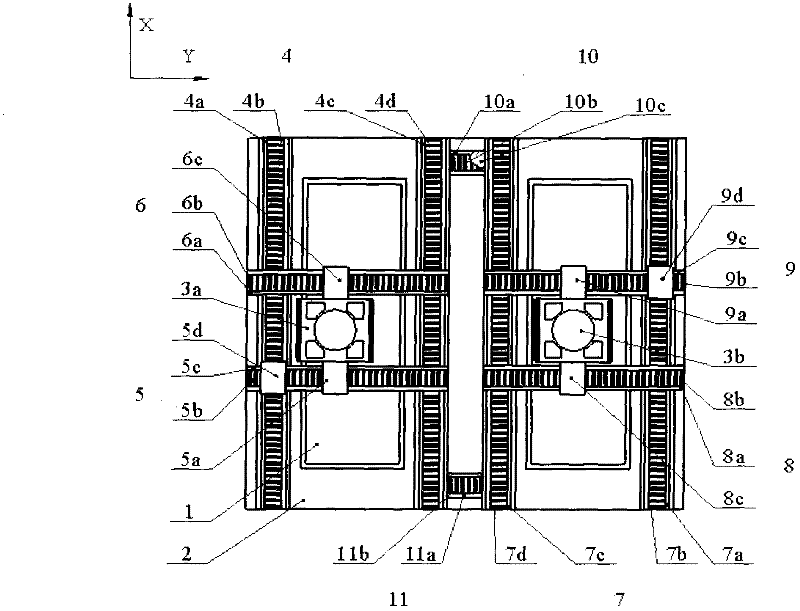
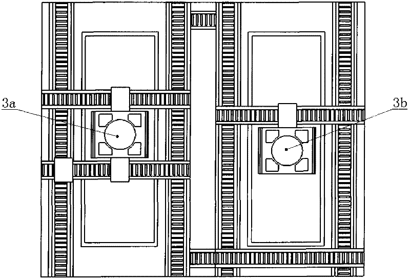
[0027] A dual-rail dual-drive step-scanning double-workpiece exchange device, the system includes a base 1, a first workpiece 3a set on the base 1 and running on an exposure station, and a pre-alignment station The second workpiece platform 3b is provided along the exposure station of the base platform 1 with the first static pressure air bearing guide rail 4a in the X direction, the first linear motor stator 4b in the X direction, the first linear motor mover 4e in the X direction, and the first linear motor mover 4e in the X direction. To the first linear motion unit 4 in the X direction composed of the second static pressure air bearing guide rail 4c, the second linear motor stator 4d in the X direction, and the second linear motor mover 4f in the X direction, the first linear motion unit 4 in the X direction It is provided with the Y-direction first linear motor mover 1 5a, the Y-direction first linear motor stator 5b, the Y-direction first static pressure air bearing guide...
Embodiment 2
[0035] Removing the X-direction second linear motor 4d, X-direction fourth linear motor 7d, Y-direction first transition linear motion unit 10 and Y-direction second linear motion unit 11 in the X-direction linear drive unit in Embodiment 1 can be implemented Example 2, such as Figure 7 shown. The station exchange process of the two workpiece platforms in embodiment 2 is exactly the same as in embodiment 1. The difference is that the X-direction driving form of the two workpiece tables is driven by a double guide rail and a single motor. Compared with Embodiment 1, the problem of inconsistency in driving the dual motors in the X direction can be avoided under the premise of ensuring the angular rigidity of the X direction movement. At the same time, due to the removal of the transitional linear motion unit, the range of motion of the double workpiece table can be increased, but the size of the X-direction linear motor will increase due to the X-direction driving force.
Embodiment 3
[0037] Remove the X-direction second linear motor 4d, the X-direction second static pressure air bearing guide rail 4c, the X-direction fourth linear motor 7d, the X-direction fourth static pressure air bearing guide rail, and the X-direction linear drive unit in the first embodiment. The first transition linear motion unit 10 in Y direction and the second linear motion unit 11 in Y direction can obtain embodiment 3, such as Figure 8 shown. The station exchange process of the two workbenches in embodiment 3 is exactly the same as that in embodiment 1. Compared with Embodiment 1, Embodiment 2 reduces the number of the X-direction second linear motor 4d, the X-direction second static pressure air bearing guide rail 4c, the X-direction fourth linear motor 7d, and the X-direction fourth linear motor 7d in the X-direction linear drive unit. The four static pressure air bearing guide rails, the first transition linear motion unit 10 in the Y direction and the second linear motion ...
PUM
 Abstract
Description
Claims
Application Information
 - R&D
- Intellectual Property
- Life Sciences
- Materials
- Tech Scout
- Unparalleled Data Quality
- Higher Quality Content
- 60% Fewer Hallucinations
Browse by: Latest US Patents, China's latest patents, Technical Efficacy Thesaurus, Application Domain, Technology Topic, Popular Technical Reports.
© 2025 PatSnap. All rights reserved.Legal|Privacy policy|Modern Slavery Act Transparency Statement|Sitemap|About US| Contact US: help@patsnap.com


