
Method For Manufacturing Optical Elements

A technology of optical elements and manufacturing methods, applied in optical elements, optical elements, optics, etc., can solve the problems of reduced productivity, complicated procedures, and inability to obtain uniformity of ink layers, and achieve cost simplification, low cost, and prevention of color mixing Effect

Inactive Publication Date: 2012-04-25
ASAHI GLASS CO LTD
View PDF56 Cites 10 Cited by
  • Summary
  • Abstract
  • Description
  • Claims
  • Application Information

AI Technical Summary

Problems solved by technology

[0009] However, although the introduction of the post-exposure process shown in Patent Document 1 is effective in improving the uniformity of the ink layer, the increase in the exposure process leads to a decrease in productivity. Therefore, a technology that can improve the uniformity of the ink layer without a post-exposure process is required.
[0010] In addition, the manufacturing method described in Example 2 of Patent Document 2 is carried out in a nitrogen atmosphere, not only the process is complicated, but also the ink layer cannot obtain sufficient uniformity.
The production method described in Example 3 of Patent Document 2 is carried out under a reduced pressure process, and the process is complicated

Method used


Image

  • Method For Manufacturing Optical Elements
  • Method For Manufacturing Optical Elements
  • Method For Manufacturing Optical Elements

Examples


Embodiment 1

[0253] (Preparation of coating liquid for negative photosensitive resin composition)

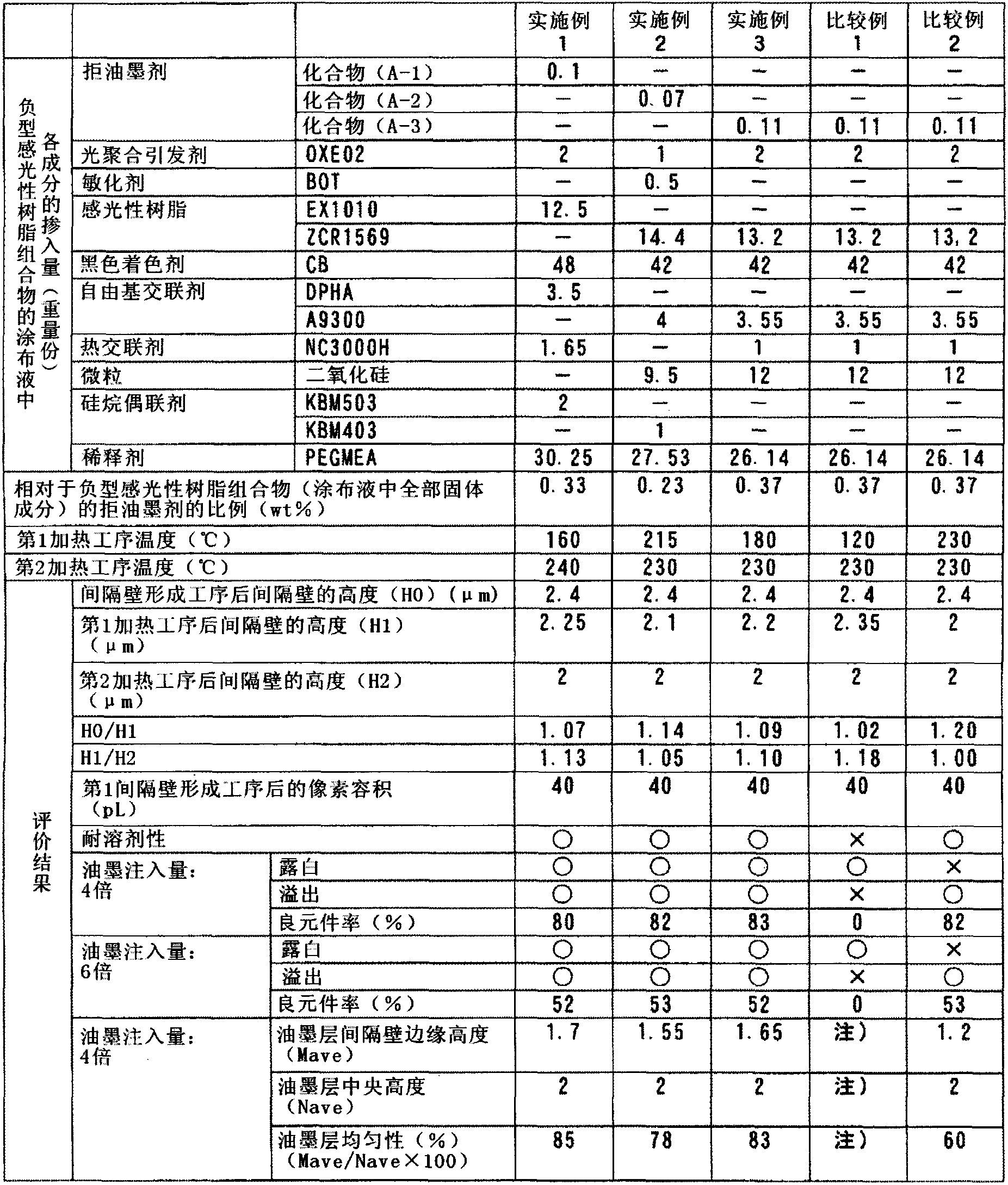
[0254] The compound (A-1) (0.10 parts) as an ink repellent agent obtained above, OXE02 (2.0 parts) as a photopolymerization initiator, EX1010 (12.5 parts) as a solution of a photosensitive resin, and a black coloring agent CB (48.0 parts) of the dispersion, DPHA (3.5 parts) as a free radical crosslinking agent, NC3000H (1.65 parts) as a thermal crosslinking agent / epoxy resin, KBM503 (2.0 parts) as a silane coupling agent, and PGMEA (30.25 parts) as a solvent was mixed to obtain a coating liquid of a negative photosensitive resin composition. The content of the ink repellent relative to the total solids in the coating liquid of the negative photosensitive resin composition, in other words, the content of the ink repellent in the negative photosensitive resin composition, that is, the content of the compound (A-1) The content is 0.33%.

[0255] Next, using the coating liquid of the negative photo...

Embodiment 2、3

[0270] The mixing amount of each component contained in the negative photosensitive resin composition coating liquid was changed to the amount shown in Table 1, and the first heating step (2) and / or the second heating step (4) were The heating temperature was changed to the temperature shown in Table 1 within the preferred range of the present invention. Except for this, the same operation as in Example 1 was carried out to obtain a test optical element, which has a function of dividing the upper surface of the glass substrate into multiple units. A partition wall composed of a cured resin and a pixel composed of a plurality of ink layers formed in a region partitioned by the partition wall on the substrate.

Embodiment 4~7、 comparative example 3

[0274] Using the mixed negative photosensitive resin composition coating liquid shown in Table 2, partition walls were produced as follows. In addition, in each example, the values ​​of H0, H1, and H2 and the volume of the opening are shown in Table 2.

[0275] (1) Partition wall formation process

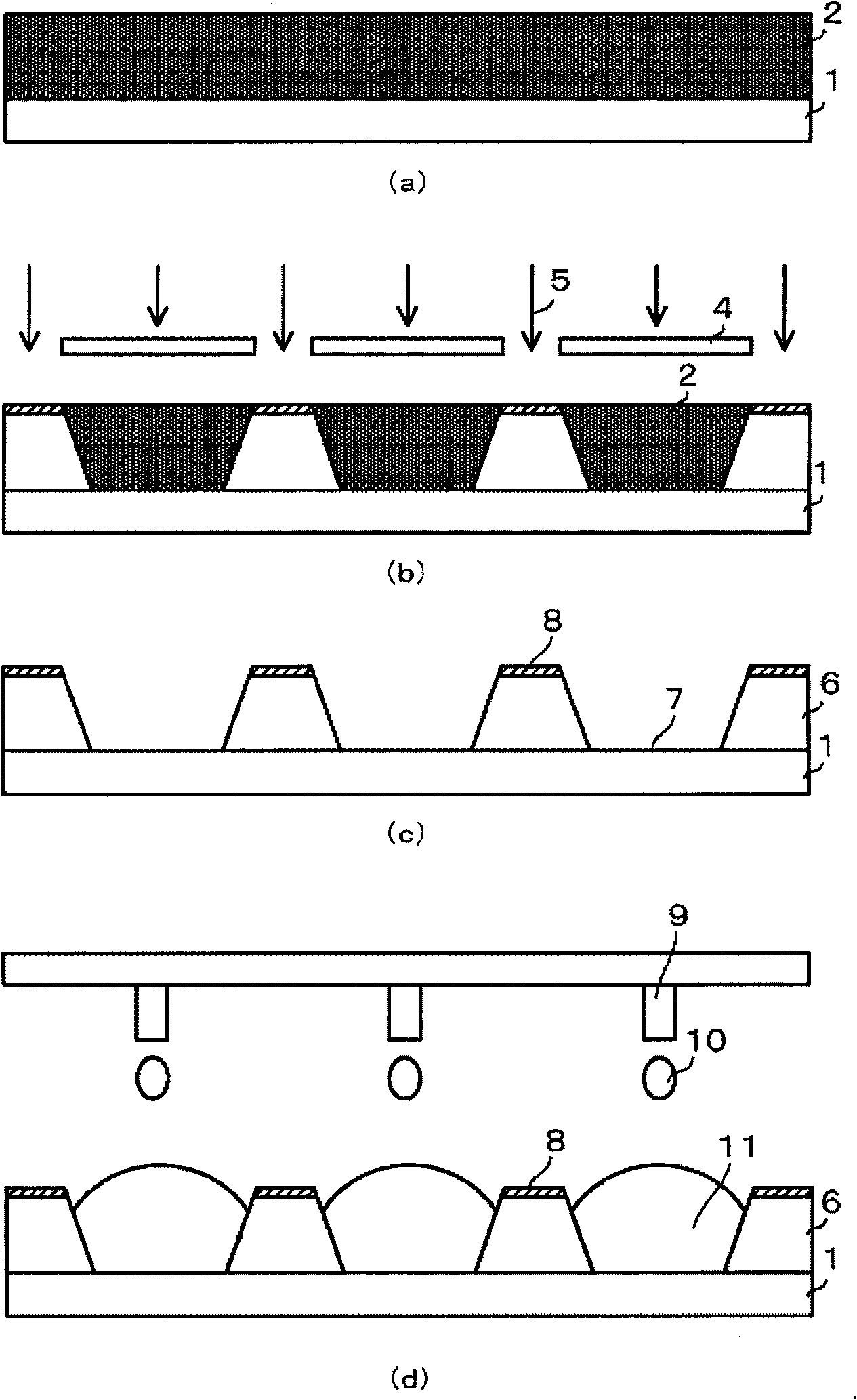
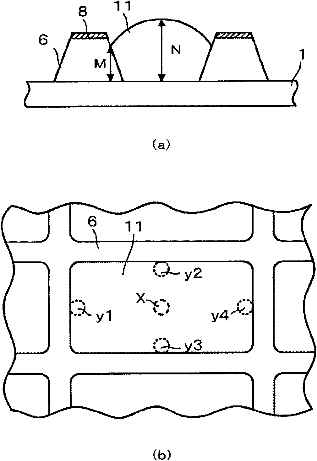
[0276] In the same manner as in Example 1, a coating film of a negative photosensitive resin composition having a film thickness of 2.4 μm was formed on the glass substrate AN100. Using an ultra-high pressure mercury lamp to irradiate the coating film of the negative photosensitive resin composition on the glass substrate obtained above through a mask, 30mW / cm based on i-line (365nm) 2 Light for 1.7 seconds at 50mJ / cm 2 Exposure at the exposure level. In addition, the mask is a grid pattern with a light-shielding part of 150 μm×300 μm and a light-transmitting part of 20 μm, and the volume of the area partitioned by the partition wall formed on the glass substrate, that is, the volume o...


PUM

PropertyMeasurementUnit
heightaaaaaaaaaa
acid valueaaaaaaaaaa

Abstract

Provided is a method for manufacturing optical elements, said method being capable of: preventing mixing of ink colors when injecting ink as part of the inkjet method, without decreasing the solvent resistance of partition walls; forming even ink layers by ensuring that pixels have a good degree of wettability with respect to the ink; maintaining sufficient heat tolerance in obtained optical elements; and being performed in a simplified and economically advantageous process. After forming, on top of a support substrate, partition walls that comprise a resin composite having an ink-repellent surface, an inkjet is used to inject ink between said partition walls, thereby manufacturing an optical element. After forming the partition walls, before and after the inkjet step, heat treatment is performed such that the thickness of the partition walls decreases by a prescribed fraction, thereby curing the resin composite that constitutes the partition walls.

Description

Technical field [0001] The present invention relates to a method of manufacturing an optical element having a plurality of pixels partitioned by partition walls, such as a color filter, an organic EL display element, and an organic TFT array. Background technique [0002] In recent years, as manufacturing methods for color filters, organic EL (Electro-Luminescence) display elements, and organic TFT (Thin Film Transistor) arrays, in order to reduce the cost of the manufacturing process, gradually Started to use the inkjet method. [0003] For example, it is known that in the manufacture of color filters, a resin composition is used to form a partition wall pattern (which also functions as a black matrix), and then R (red) and G ( Green) and B (blue) inks to form pixels. [0004] In addition, it is also known that in the manufacture of organic EL elements, a resin composition is used to form a partition wall pattern, and then a solution of hole transport material, luminescent materia...

Claims


Application Information

Patent Timeline
Patent Type & Authority Applications(China)
IPC IPC(8): G02B5/20G02F1/1335G02F1/1339G03F7/004G03F7/40H01L51/50H05B33/10H05B33/12H05B33/22
CPCB29D11/00298G03F7/0007G03F7/033G03F7/40G03F7/0758H01L51/0005B29D11/00634G02B5/223G03F7/0046G03F7/0388B41J2202/09G02B5/201H10K71/135H10K10/46
Inventor 高桥秀幸石関健二川岛正行
Owner ASAHI GLASS CO LTD
Learn More