Integrated system on ultrasonic transducer sheet with MEMS (Micro-Electromechanical Systems) glass sphere and preparation method thereof

An on-chip integrated system and ultrasonic transducer technology, applied in the field of microfluidics, can solve the problems of difficult to achieve on-chip integration and low efficiency, and achieve the effect of high molding height, simple method and low cost

Active Publication Date: 2012-05-02
SOUTHEAST UNIV
View PDF4 Cites 7 Cited by
  • Summary
  • Abstract
  • Description
  • Claims
  • Application Information

AI Technical Summary

Problems solved by technology

[0006] The problem with existing technology is that fluids typically need to be taken from the microfluidic ...

Method used


Image

  • Integrated system on ultrasonic transducer sheet with MEMS (Micro-Electromechanical Systems) glass sphere and preparation method thereof
  • Integrated system on ultrasonic transducer sheet with MEMS (Micro-Electromechanical Systems) glass sphere and preparation method thereof
  • Integrated system on ultrasonic transducer sheet with MEMS (Micro-Electromechanical Systems) glass sphere and preparation method thereof

Examples


Embodiment 1

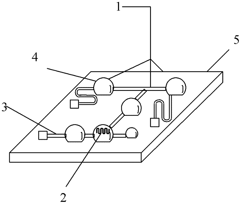
[0026] A method for preparing a microfluidic grid on-chip experimental system integrating a spherical glass cavity focused ultrasonic transmitter, comprising the following steps:

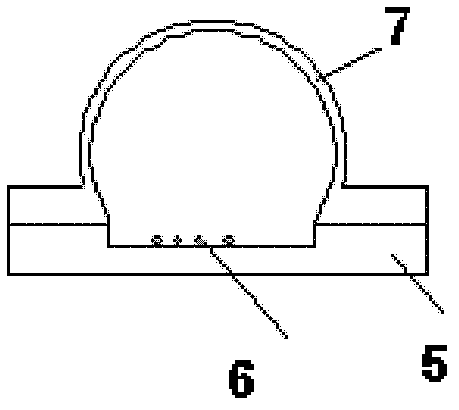
[0027] In the first step, a 5000A oxide layer is oxidized on a single-sided polished silicon wafer by a combination of dry and wet oxygen, and the polished surface is spin-coated with AZ P4620 photoresist, exposed and developed to remove the photoresist that needs to be etched on the surface of the microcavity. Utilize Si micromachining process to etch the microcavity and microchannel shallow cavity on the 4-inch Si wafer, and the microchannel connects the shallow cavity. The depth of the cavity is 60-100 microns, the micro-cavity is a square or circular cavity with a width of 1000-5000 microns, the micro-channel cavity is a strip-shaped cavity with a diameter of 50 microns, and the length of the cavity is 5 mm. Cavity square cavity, the micromachining process of the pattern structure on the Si wafe...

Embodiment 2

[0035] A method for preparing a microfluidic grid on-chip experimental system integrating a spherical glass cavity focused ultrasonic transmitter, comprising the following steps:

[0036] In the first step, a 5000A oxide layer is oxidized on a single-sided polished silicon wafer by a combination of dry and wet oxygen, and the polished surface is spin-coated with AZ P4620 photoresist, exposed and developed to remove the photoresist that needs to be etched on the surface of the microcavity. Utilize Si micromachining process to etch the microcavity and microchannel shallow cavity on the 4-inch Si wafer, and the microchannel connects the shallow cavity. The depth of the cavity is 60-100 microns, the micro-cavity is a square or circular cavity with a width of 1000-5000 microns, the micro-channel cavity is a strip-shaped cavity with a diameter of 50 microns, and the length of the cavity is 5 mm. Cavity square cavity, the micromachining process of the pattern structure on the Si wafe...


PUM

PropertyMeasurementUnit
Radiusaaaaaaaaaa
Thicknessaaaaaaaaaa
Thicknessaaaaaaaaaa

Abstract

The invention discloses a preparation method of an experimental system on a micro-runner grid sheet of a focusing ultrasonic transmitter integrated with spherical glass cavity, comprising the steps of: 1, preparing a spherical glass micro-cavity or a cylindrical micro-runner by a thermal forming method; 2, integrating vibration and excitation sources such as a metal strip on the prepared spherical glass micro-cavity or cylindrical micro-runner; 3, placing biological cells or molecules in the experimental system on the glass micro-runner grid integrated sheet with the excitation sources; and 4, treating the biological cells or molecules by the experimental system on the integrated sheet. The invention generates resonance with frequency which is 20kHz-1MHz based on the glass sphere cavity under external electric excitation or electromagnetic excitation. The frequency range of the resonance frequency is ultrasonic range. Cavitation effect generated by ultrasonic wave can be applied to micro-treatment in the field of biology or chemistry, such as cell disruption and DNA interruption and the like.

Description

technical field [0001] The invention relates to a microfluidic control technology, in particular to a MEMS glass spherical ultrasonic transducer on-chip integrated system and a preparation method thereof. Background technique [0002] The 21st century is a century in which biotechnology will be highly developed. After years of practice, bioanalysis and detection technology has gradually developed and matured. In the process of biological analysis and detection, samples in single molecule or cell detection experiments need to be pretreated, crushed, separated, reacted, analyzed and detected in different conditions and equipment due to the different molecular sizes. If the various steps of the whole experimental process can be integrated, the efficiency of biological experiments and the yield of experimental products will be greatly improved, and the accuracy of experiments will be improved at the same time. [0003] High-intensity focused ultrasound (HIFU for short) technolo...

Claims


Application Information

Patent Timeline
IPC IPC(8): B06B1/02B81B7/02B81C1/00G01N35/00
Inventor 尚金堂罗新虎秦顺金
Owner SOUTHEAST UNIV
Why Eureka
Try Eureka