Optical fiber bundle spectrometer

A fiber optic bundle and spectrometer technology, applied in the field of spectral radiation measurement, can solve problems such as inability to obtain accurate spectral images, nonlinear and dark noise errors, long detector integration time, etc., to achieve multi-purpose spectral measurement, linearity error and dark Effect of reduced noise error and high measurement accuracy

Active Publication Date: 2012-05-02
HANGZHOU EVERFINE PHOTO E INFO
View PDF6 Cites 26 Cited by
  • Summary
  • Abstract
  • Description
  • Claims
  • Application Information

AI Technical Summary

Problems solved by technology

[0004] However, the existing optical fiber bundle spectrometer has the following defects: the incident slit only allows a small amount of light emitted from the optical fiber or optical fiber bundle to enter the spectrometer dark box to participate in the measurement, while most of the sampled optical signals do not participate in the measurement, resulting in the spectrometer The sensitivity of the detector is low, this problem is particularly prominent in the measurement of weak light, which will bring a large measurement error, and the low sensitivity means that the integration time of the detector is generally longer in the measurement, and it is easy to bring nonlinearity and Larger errors such as dark noise
The above methods also have the problems of high cost and long measurement time. If the luminescence of the measured target changes rapidly with time, an accurate spectral image cannot be obtained at all.

Method used


Image

  • Optical fiber bundle spectrometer
  • Optical fiber bundle spectrometer
  • Optical fiber bundle spectrometer

Examples


Embodiment 1

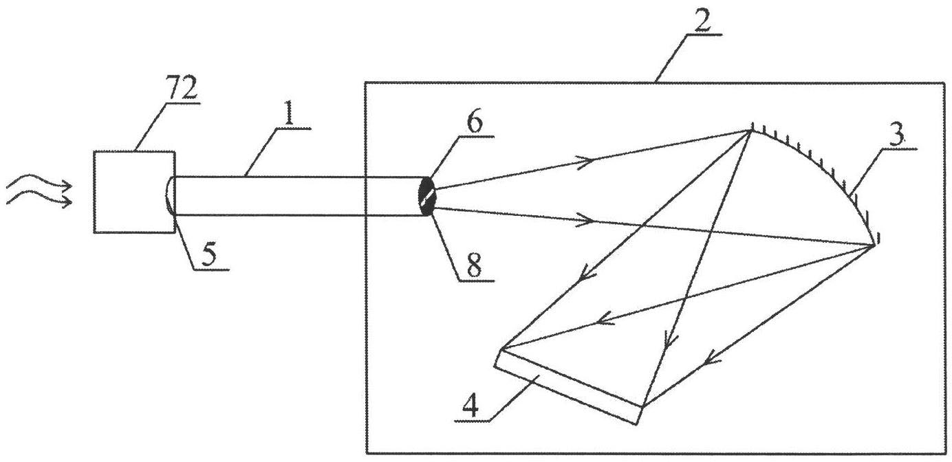
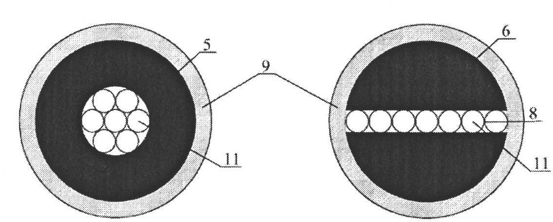
[0038] Embodiment 1 of the present invention such as figure 1 As shown, it includes an optical fiber bundle 1 and a spectrometer obscura 2, and the optical fiber bundle 1 is an optical signal input element of the optical fiber bundle spectrometer. The optical sampling device in this embodiment is an optical mixer 72 , which fully mixes the optical signal of the object to be measured and then inputs it to the input end 5 of the optical fiber bundle 1 and transmits it to the dark box 2 . A dispersion element 3 and an array detector 4 are arranged in the dark box, the dispersion element 3 is a flat-field concave grating, and the array detector 4 is a CCD. Such as figure 2 As shown, the optical fiber bundle 1 includes a plurality of optical fiber units 11 and the optical fiber protection layer 9, each optical fiber unit 11 corresponds to an optical fiber, the input end of the optical fiber bundle 1 is arranged in a circle, and the optical fiber unit in the output end 6 of the op...

Embodiment 2

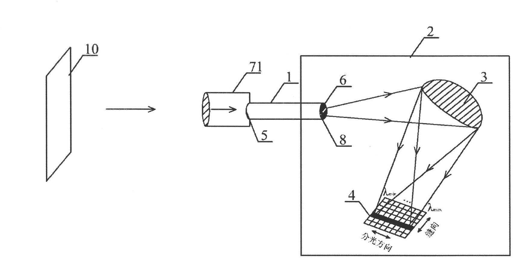
[0040] Such as image 3 Shown is embodiment 2 of the present invention, the optical fiber bundle spectrometer in embodiment 2 comprises imaging device 71, optical fiber bundle 1 and spectrometer dark box 2, is provided with dispersive element 3 and array detector 4 in dark box 2, wherein dispersive element 3 It is a flat-field concave grating, and the array detector 4 is a two-dimensional array detector. The fiber bundle output ends 6 in Embodiment 2 are arranged into optical slits 8 , and the sum of the optical slits 8 is perpendicular to the light splitting direction of the dispersive element 3 . During measurement, the imaging device 71 images the measured object 10 onto the input end 5 of the optical fiber bundle, and the optical slit 8 at the output end 6 of the optical fiber bundle couples the measured optical signal to the dispersive element 3, and after being split by the dispersive element 3, it is The two-dimensional array detector 4 receives and measures. The two-...

Embodiment 3

[0046] Such as Figure 8Shown is Example 3 of the present invention. The fiber bundle spectrometer in Embodiment 3 includes a fiber bundle 1, a spectrometer dark box 2 and a plurality of integrating spheres 72-1, 72-2, 72-3. The structure of the dark box 2 in this embodiment is the same as that in Embodiment 2. The fiber bundle 1 in the present embodiment is a bifurcated fiber bundle with 3 input ends 5 and an output end 6, each input end is connected with an integrating sphere 72, and a measured object is lighted in each integrating sphere 72 The light source 10, therefore, each input port 5 collects the signals of each light source 10 under test respectively, and introduces all optical signals into the dark box 2 through the optical slit 8 at the output end 6 of the optical fiber bundle for spectral measurement. In the two-dimensional array detector 4, pixels of different spatial dimensions correspond to the measurement of light signals from different light sources under t...


PUM


Abstract

The invention discloses an optical fiber bundle spectrometer, which comprises an optical fiber bundle, a dispersion element and an array detector element, wherein an output end of the optical fiber bundle is arranged into an optical slit, is fixedly arranged on an incident light path of the dispersion element, and is directly used as an incident slit of the spectrometer, the energy loss of a sampling optical signal can be greatly reduced, the instrumental sensitivity is greatly improved, as a result, the nonlinearity, the dark noise and the stray light error of the instrument are reduced, and higher measurement accuracy and quicker measurement velocity are obtained. Through orderly arranging a two-dimensional array detector and optical fiber units at the input end and the output end of the optical fiber bundle and connecting a plurality of sets of sub-fiber bundle spectrometer in parallel, the two-dimensional image spectra measurement and multi-purpose spectral measurement can be realized through the optical fiber bundle spectrometer, so the optical fiber bundle spectrometer has the advantages of dispensing with mechanical scanning or switching mechanism, and having quick measurement speed, high precision, flexible configuration, wide application range and the like.

Description

【Technical field】 [0001] The invention belongs to the field of spectral radiation measurement, in particular to an optical fiber bundle spectrometer using an array detector. 【Background technique】 [0002] Spectroscopy is a technique for measuring the intensity of light in the ultraviolet, visible, near-infrared, and infrared bands. Spectral measurement has a wide range of applications, such as color measurement, concentration measurement of chemical components, electromagnetic radiation analysis, light source luminescence, and aerospace spectral analysis. [0003] Optical fiber bundle spectrometers usually use optical fiber bundles as optical signal receiving and coupling devices. Because of their convenience, they have been widely used in fast spectrometers using array detectors. The basic principle is: an optical fiber bundle composed of multiple optical fibers is used as an optical signal input The component, which introduces the measured optical signal into the spectro...

Claims


Application Information

Patent Timeline
IPC IPC(8): G01J3/28
CPCG01J3/0221G01J3/18G01J3/2823
Inventor 潘建根
Owner HANGZHOU EVERFINE PHOTO E INFO
Why Eureka
Try Eureka