Field programmable gate array (FPGA)-based general wave beam forming device

A beam and generation unit technology, applied in the field of general structures, can solve problems such as weak versatility and singleness, and achieve the effects of improving signal processing capability, flexible control, and cost saving

Active Publication Date: 2013-07-24
UNIV OF ELECTRONICS SCI & TECH OF CHINA +1
View PDF3 Cites 1 Cited by
  • Summary
  • Abstract
  • Description
  • Claims
  • Application Information

AI Technical Summary

Problems solved by technology

[0005] The technical problem to be solved by the present invention is to provide a general-purpose beamforming device based on FPGA in view of the disadvantages that the prior art beamforming device can only perform beamforming of a single shape, and its versatility is not strong.

Method used


Image

  • Field programmable gate array (FPGA)-based general wave beam forming device
  • Field programmable gate array (FPGA)-based general wave beam forming device
  • Field programmable gate array (FPGA)-based general wave beam forming device

Examples


Embodiment 1

[0036] In this example, an FPGA-based general-purpose beamforming device is used to form a narrowband beamformer. The basic principle of narrowband beamforming is: the signals received by M array elements are used as the input of the M-order spatial filter, and the filter weight vector can be expressed as w=[w 1 w 2 L w M ] T , the plane wave s(n) with an angle of q is incident on the array, regardless of the influence of the receiver noise, at this time the received signal of the array is x(n)=a(q)s(n), where a(q) is any Array flow type. Then the output of the filter is y(n)=w H x(n)=w H a(q)s(n), by changing the weight vector w of the filter, the amplitude of the output signal can be changed or the signals in some directions can be passed, while the signals in other directions can be suppressed.

[0037] In narrowband mode of operation, the beamformer such as image 3 shown.

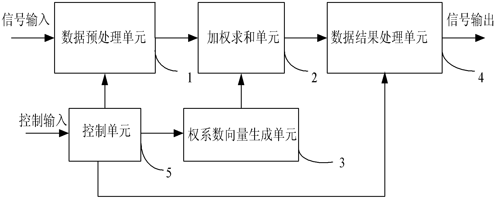
[0038]The functions of each functional unit are described as follows:

[0039] In the da...

Embodiment 2

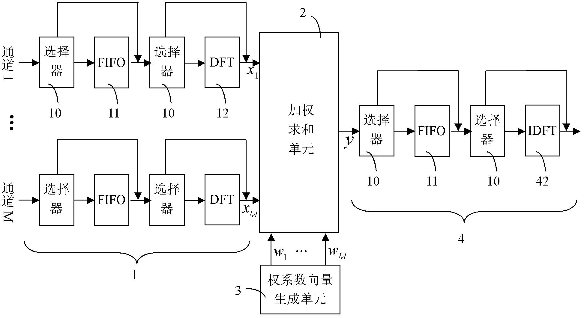
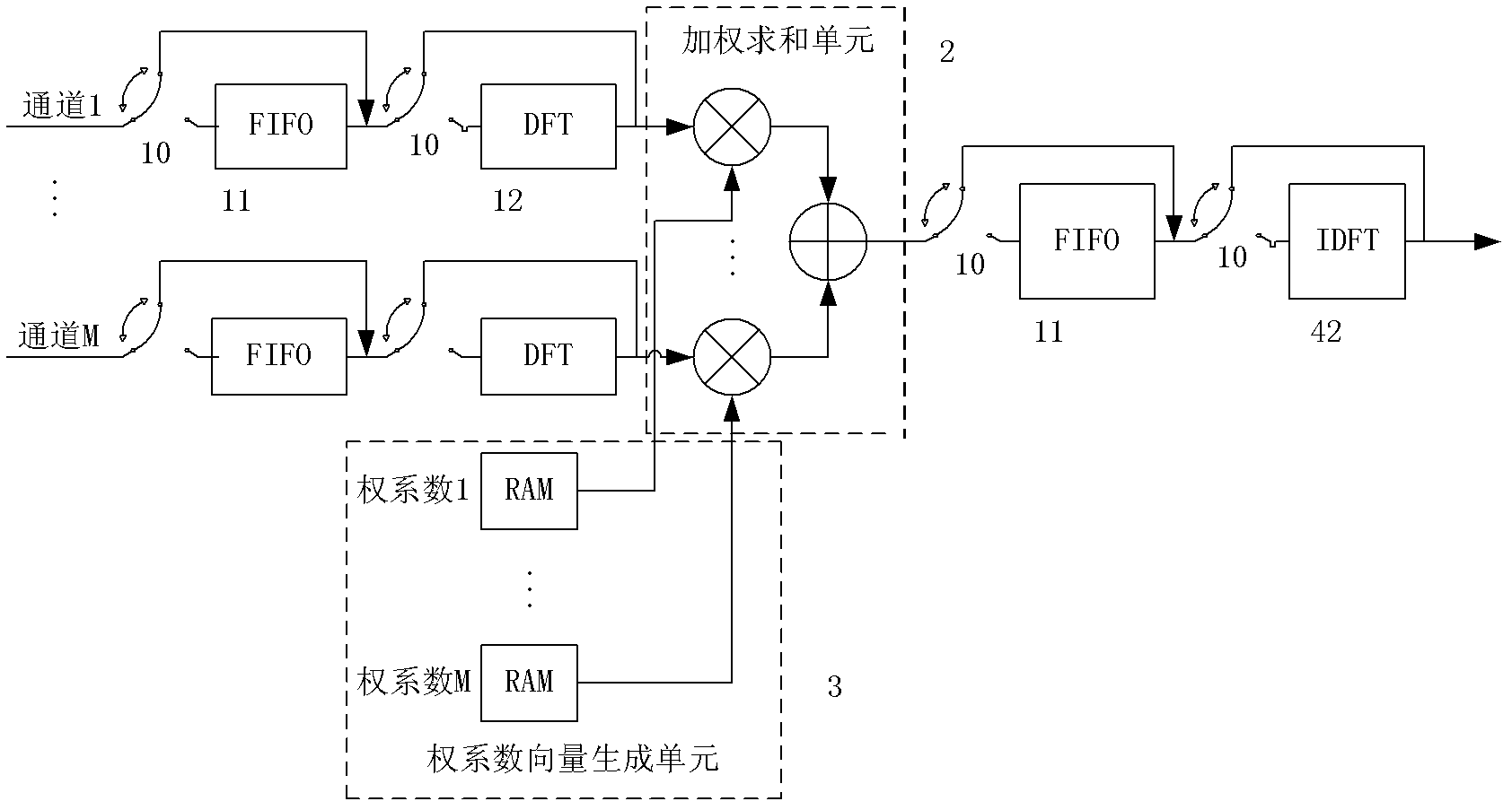
[0050] In this example, an FPGA-based general-purpose beamforming device is used to form a broadband beamformer. The basic principle of broadband beamforming: M array elements are decomposed into several sub-frequency bands through discrete Fourier transform in the frequency domain, then beamforming is performed in each sub-frequency band, and finally the output signal is obtained through inverse discrete Fourier transform. The array output data vector x(n) is decomposed into J non-overlapping narrowband parts through DFT. f j The data vector obtained on the frequency band is X(j), and the weighted summation of X(j) and W(j) can obtain the beamforming result on each frequency band, and the results obtained by processing all sub-bands can be obtained by IDFT on the entire frequency band overall result.

[0051] In wideband mode of operation, the beamformer such as Figure 4 shown.

[0052] The functions of each functional unit are described as follows:

[0053] In the data...

Embodiment 3

[0064] In this example, an FPGA-based general-purpose beamforming device is used to form a multi-beamformer. The basic principle of multi-beamforming: After processing the data of M array elements, there will be output results in different directions. The input data vector x(n) is weighted and summed with N groups of different weight vectors w, and N groups of results can be obtained. are the data of the input signal after spatial filtering in N different directions, respectively.

[0065] In the multi-beam working mode, the beamformer structure is as follows Figure 5 shown.

[0066] The functions of each functional unit are described as follows:

[0067] In the data preprocessing unit 1, the control unit connects the FIFO buffer 11 through the multiplexer 10, bypasses the DFT operator 12, and the input signal can pass through the FIFO data buffer, and the depth of the FIFO buffer is set to L. The input data sequence is divided into data blocks with length L, and each data...


PUM


Abstract

The invention relates to an array signal processing technology. Aiming at the defect of the existing wave beam forming device such as low generality since only a single-shaped wave beam can be formed, the invention discloses a field programmable gate array (FPGA)-based common wave beam forming device. The device comprises a data preprocessing unit 1, a weighting and summing unit 2, a weight coefficient vector quantity generating unit 3, a data result processing unit 4, a control unit 5 and a multi-path selector 10. The device controls whether a buffer, an arithmetic device and a reversed arithmetic device are accessed by the multi-path selector, so that output wave beam-forming data can be controlled, and narrow-band wave beam, wide-band wave beam and multi-beam wave beam can be output. The device is used for generating various wave beam-forming data by a general structure, so that the device is flexible to control, the signal processing capability of a system is improved, and the device is good for the function expanding and updating of the system. Simultaneously, the development period can be shortened, and the cost can be saved by a general wave beam forming structure.

Description

technical field [0001] The invention relates to an array signal processing technology, in particular to a general structure in which various beam forming technologies are efficiently realized in FPGA. Background technique [0002] As an important branch of array signal processing, beamforming is applied in various national economic and military applications such as radar, sonar, communication, seismic exploration, radio astronomy, and medical diagnosis. The meaning of beamforming refers to forming the main beam in a specific direction to generate useful desired signals, which is a processing system of spatial filtering. The airspace signal received by the system is usually polluted by noise or interference sources. If the interference signal and the desired signal are in the same frequency band, the time domain filter alone cannot distinguish the signal from the interference. However, the desired signal and the interference signal Usually beams from different azimuths, so s...

Claims


Application Information

Patent Timeline
Patent Type & Authority Patents(China)
IPC IPC(8): G01S7/52G01S7/02H04B7/04G06F9/46
Inventor 李会勇贾可新王学斌王波谢菊兰安琦何子述莫启旭梁福坤
Owner UNIV OF ELECTRONICS SCI & TECH OF CHINA
Why Eureka
Try Eureka