Method for selecting decoupling condenser based on particle swarm algorithm
A decoupling capacitor and particle swarm algorithm technology, which is applied in the fields of instrumentation, calculation, electrical and digital data processing, etc., can solve the problems of unintuitive selection results, low degree of automation, and long simulation time, so as to achieve intuitive selection results and improve the degree of automation. , the effect of shortening the simulation time
- Summary
- Abstract
- Description
- Claims
- Application Information
AI Technical Summary
Problems solved by technology
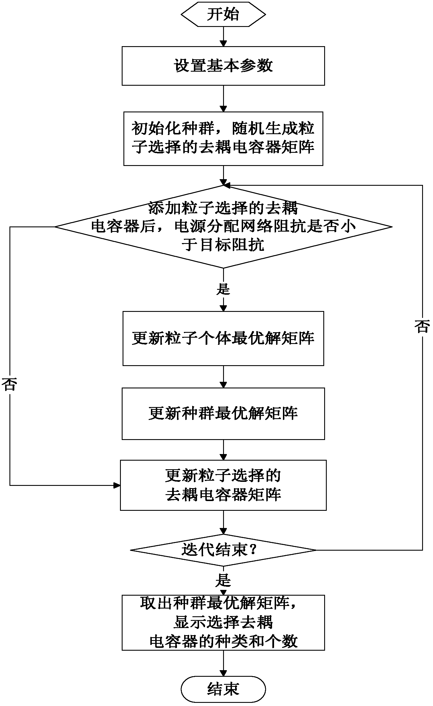
Method used
Image
Examples
Embodiment 1
[0065] Set the basic parameters as follows:
[0066] The equivalent resistance R1 of the regulator on the printed circuit board is 0.001Ω, and the equivalent inductance L1 is 30nH;
[0067] The equivalent resistance R2 of the printed circuit board power / ground plane is 0.003Ω, and the equivalent capacitance C1 is 2.6nF;
[0068] The number of vias on the printed circuit board is 200;
[0069] The maximum current I of the integrated chip is 2A, the power supply voltage V1 is 2.5V, the ripple coefficient r is 3%, and the target frequency is 100MHz.
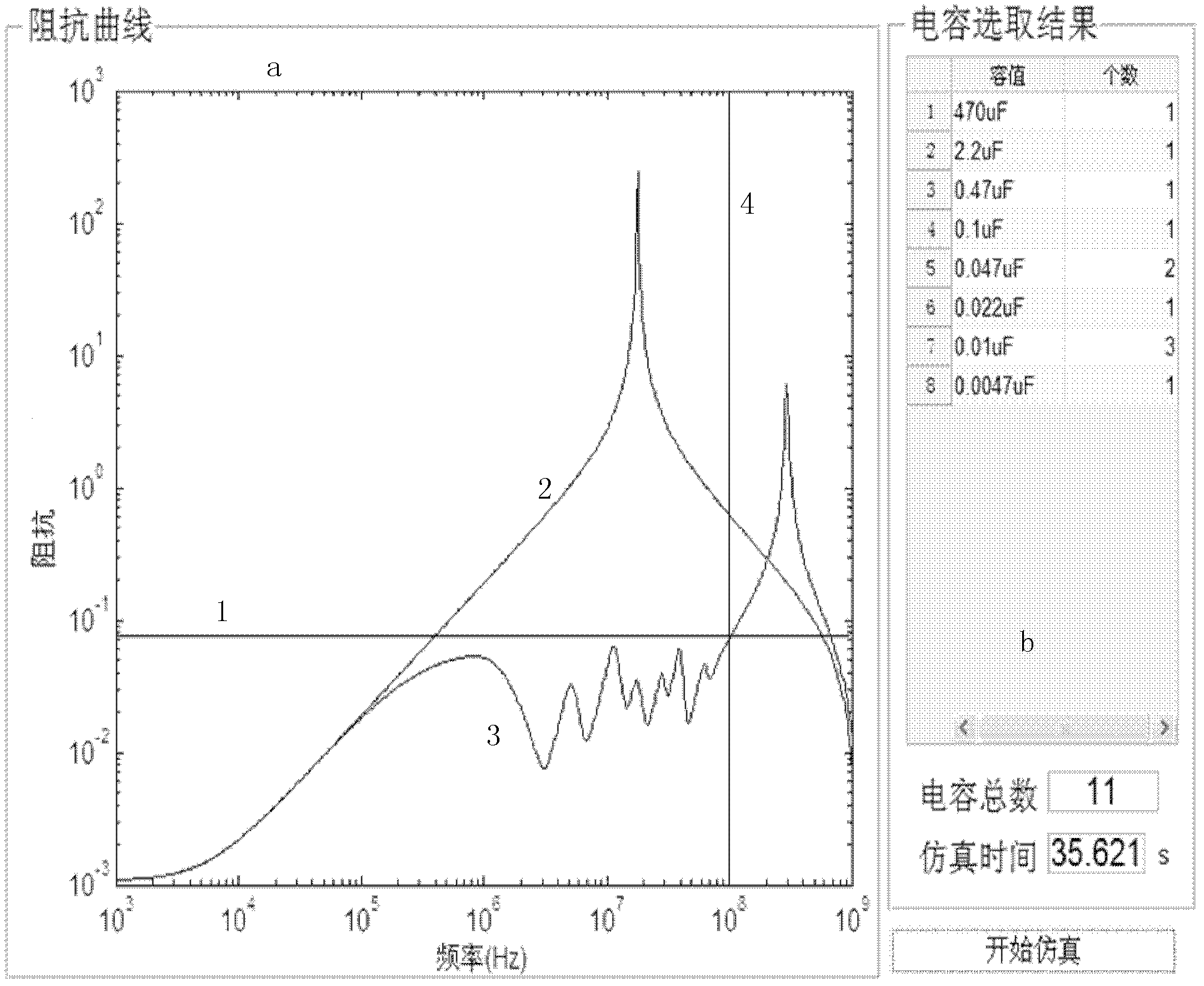
[0070] Based on the above parameters, the implementation steps of the present invention are used to simulate the particle swarm algorithm-based decoupling capacitor selection method proposed by the present invention through MATLAB 7.11.0 software. The simulation results are as follows: figure 2 ,in: figure 2 a is the impedance curve of the power distribution network, figure 2 b is the decoupling capacitor selection result.
...
Embodiment 2
[0074] Set the basic parameters as follows:
[0075] The equivalent resistance R1 of the regulator on the printed circuit board is 0.003Ω, and the equivalent inductance L1 is 25nH;
[0076] The equivalent resistance R2 of the printed circuit board power / ground plane is 0.004Ω, and the equivalent capacitance C1 is 3nF;
[0077] The number of vias on the printed circuit board is 160;
[0078] The maximum current I of the integrated chip is 2A, the power supply voltage V1 is 3.3V, the ripple coefficient r is 3%, and the target frequency is 120MHz.
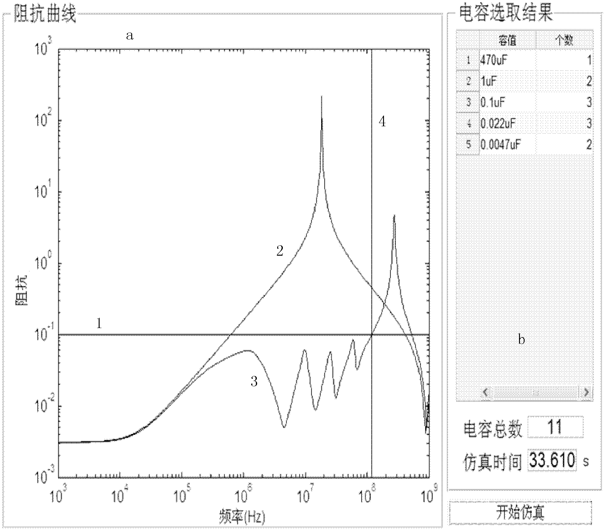
[0079] Based on the above parameters, the implementation steps of the present invention are used to simulate the particle swarm algorithm-based decoupling capacitor selection method proposed by the present invention through MATLAB 7.11.0 software. The simulation results are as follows: image 3 ,in: image 3 a is the impedance curve of the power distribution network, image 3 b is the decoupling capacitor selection result.
[008...
Embodiment 3
[0083] Set the basic parameters as follows:
[0084] The equivalent resistance R1 of the regulator on the printed circuit board is 0.002Ω, and the equivalent inductance L1 is 35nH;
[0085] The equivalent resistance R2 of the printed circuit board power / ground plane is 0.002Ω, and the equivalent capacitance C1 is 2nF;
[0086] The number of vias on the printed circuit board is 100;
[0087] The maximum current I of the integrated chip is 2A, the power supply voltage V1 is 1.8V, the ripple coefficient r is 3%, and the target frequency is 80MHz.
[0088] Based on the above parameters, the implementation steps of the present invention are used to simulate the particle swarm algorithm-based decoupling capacitor selection method proposed by the present invention through MATLAB 7.11.0 software. The simulation results are as follows: Figure 4 ,in: Figure 4 a is the impedance curve of the power distribution network, Figure 4 b is the decoupling capacitor selection result.
[0...
PUM
| Property | Measurement | Unit |
|---|---|---|
| Equivalent resistance | aaaaa | aaaaa |
| Equivalent resistance | aaaaa | aaaaa |
| Equivalent capacitance | aaaaa | aaaaa |
Abstract
Description
Claims
Application Information
 - R&D
- Intellectual Property
- Life Sciences
- Materials
- Tech Scout
- Unparalleled Data Quality
- Higher Quality Content
- 60% Fewer Hallucinations
Browse by: Latest US Patents, China's latest patents, Technical Efficacy Thesaurus, Application Domain, Technology Topic, Popular Technical Reports.
© 2025 PatSnap. All rights reserved.Legal|Privacy policy|Modern Slavery Act Transparency Statement|Sitemap|About US| Contact US: help@patsnap.com


