Three-frequency frequency reconfigurable antenna for coplanar waveguide feed

A technology of coplanar waveguide and reconstructed antenna, which is applied to antennas, antenna grounding devices, and devices that make antennas work in different frequency bands at the same time. Effects of reduced influence of characteristics, good impedance matching, and high availability

Inactive Publication Date: 2012-05-02
SHANGHAI UNIV
View PDF4 Cites 22 Cited by
  • Summary
  • Abstract
  • Description
  • Claims
  • Application Information

AI Technical Summary

Problems solved by technology

Considering the support and integration of wireless communication equipment for various communication standards and the new communication standards in the future, the disadvantages of this solution are: the number of antennas is large, the spectrum utilization rate is small, the equipment volume is increased, and the cost is high. large interference

Method used


Image

  • Three-frequency frequency reconfigurable antenna for coplanar waveguide feed
  • Three-frequency frequency reconfigurable antenna for coplanar waveguide feed
  • Three-frequency frequency reconfigurable antenna for coplanar waveguide feed

Examples


Embodiment 1

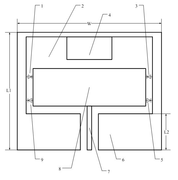
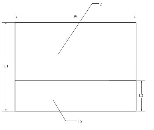
[0034] Embodiment one: see figure 1 , the coplanar waveguide-fed tri-frequency frequency reconfigurable antenna includes an upper metal microstrip, a middle dielectric substrate 2 and a lower back floor 10, the metal microstrip includes a radiation patch 8, and a coplanar waveguide floor 6. Coplanar waveguide feeder 7, matching branch 4 and four PIN diodes 1, 3, 5, 9, the coplanar waveguide floor 6 surrounds the radiation patch 8, and the coplanar waveguide floor 6 and the radiation patch are separated by Four PIN diodes 1, 3, 5, and 9 are connected, the coplanar waveguide feeder 7 is located at the central opening under the coplanar waveguide floor 6 and is integrated with the radiation patch 8, and the matching branch 4 is integrated with the upper part of the coplanar waveguide floor 6 The back floor 10 is a metal coating located on the back of the dielectric substrate 2 corresponding to the lower part of the coplanar waveguide floor 6 and below the coplanar waveguide feede...

Embodiment 2

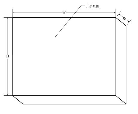
[0035] Embodiment two: see figure 1 and figure 2 , this embodiment is basically the same as Embodiment 1, and the special features are as follows: the size of the dielectric substrate (2) is 95mm*110mm*0.8mm, the upper layer and the lower layer are metal coating, and the material is copper.

Embodiment 3

[0036] Embodiment 3: The tri-frequency frequency reconfigurable antenna fed by the coplanar waveguide is divided into upper, middle and lower layers. upper as figure 1 As shown, it is composed of metal microstrip antenna and RF PIN diodes 1, 3, 5, and 9; the lower layer is as figure 2 Consists of metal back floor as shown; intermediate layer as image 3 Shown is the dielectric substrate 2 used in this embodiment, with a thickness H.

[0037]This antenna has a left-right symmetrical structure. The coplanar waveguide floor 6 and the coplanar waveguide feeder 7 constitute the feeding form of the coplanar waveguide. At the same time, there is a layer of back floor 10 on the other side of the dielectric substrate 2 corresponding to it, which is a metal Plating, the above constitute the feeder structure of the present invention. In the three operating frequency bands, the characteristic impedance of the feeder is approximately equal to 50 ohms, so that the connection of the feed...


PUM


Abstract

The invention relates to a three-frequency frequency reconfigurable antenna for coplanar waveguide feed, which comprises a metal microstrip on the upper layer, a dielectric substrate on the middle layer and a back floor board on the lower layer. The metal microstrip comprises a radiating patch, a coplanar waveguide floor board, a coplanar waveguide feeder, a matching branch and four PIN (P-Intrinsic-N) diodes, and the radiating patch is surrounded by the coplanar waveguide floor board. The coplanar waveguide floor board is connected with the radiating patch through the four PIN diodes, the coplanar waveguide feeder is arranged at a central opening on the lower edge of the coplanar waveguide floor board and is connected with the radiating patch into a whole, and the matching branch is connected with the upper part of the coplanar waveguide floor board into a whole. The back floor board is arranged on the back of the dielectric substrate and corresponds to metal coatings on the lower part of the coplanar waveguide floor board and under the coplanar waveguide feeder, and a microstrip antenna is formed by the back floor board and the metal microstrip. The three-frequency frequency reconfigurable antenna can work on three wireless communication frequency bands of 0.9GHz, 1.8GHz and 2.4GHz. Moreover, directional diagrams on the three frequency bands basically remain unchanged and have larger bandwidth. Meanwhile, the design of a switch bias circuit can be eliminated, and the impact of a switch on the radiation performance of the antenna can be reduced.

Description

technical field [0001] The invention relates to a three-frequency reconfigurable microstrip antenna fed by a coplanar waveguide. The invention belongs to the category of a frequency reconfigurable antenna with multiple adjustable frequencies in the field of wireless communication. Background technique [0002] Today's wireless communication technology is developing rapidly, as long as there is wireless network coverage, people can freely communicate with others or transmit data. New wireless technologies are constantly emerging, and the wireless frequency bands used are constantly being updated. For example, GSM900 system, DCS1800 system, 3G wireless communication system, WLAN wireless local area network system, WiMAX and other systems all use different radio spectrum. A common solution at present is to erect multiple corresponding antennas on the system equipment. Considering the support and integration of wireless communication equipment for various communication standa...

Claims


Application Information

Patent Timeline
Patent Type & Authority Applications(China)
IPC IPC(8): H01Q1/38H01Q1/48H01Q5/01H01Q13/08H01Q5/10
Inventor 杨雪霞邵秉成姚望熊晗
Owner SHANGHAI UNIV
Why Eureka
Try Eureka