Wireless temperature and humidity monitoring device for high-voltage switch cabinet
A technology for wireless temperature and humidity monitoring of cabinets, applied in the field of wireless temperature and humidity monitoring devices for high-voltage switch cabinets, can solve problems such as communication reliability decline, lithium battery capacity limitation, electrolyte leakage, etc., to avoid overheating of equipment contacts and low heat generation , the effect of improving the level of automation
- Summary
- Abstract
- Description
- Claims
- Application Information
AI Technical Summary
Problems solved by technology
Method used
Image
Examples
Embodiment 1
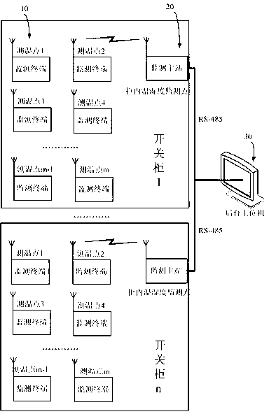
[0019] Embodiment 1, with reference to Figure 1-4 , a wireless temperature and humidity monitoring device for a high-voltage switchgear, which includes a plurality of monitoring terminals, a plurality of monitoring master stations and a background host computer; each switchgear is equipped with a monitoring master station and a plurality of monitoring terminals, and the monitoring master station and Two frequency band radio frequency communication modules of 433M and 2.4G are used for data transmission between monitoring terminals; RS-485 communication is used between the monitoring master station and the host computer;
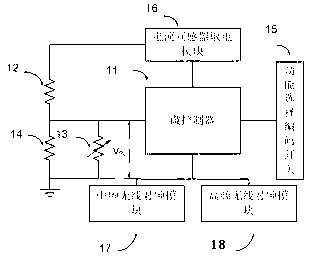
[0020] The monitoring terminal consists of a microcontroller STM32, a thermistor MF51, a precision trimmer potentiometer, a voltage divider resistor, a function selection code switch, a current transformer power supply module, a 433M intermediate frequency radio frequency module SI4432, and a 2.4G high frequency radio frequency module. The module CC2520 is c...
Embodiment 2
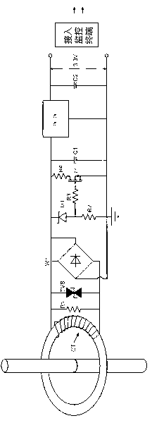
[0022] Embodiment 2, in the high-voltage switchgear wireless temperature and humidity monitoring device described in Embodiment 1: the monitoring terminal is powered by a current transformer power supply module with overvoltage protection, and the current transformer power supply module is composed of a sampling resistor R1, a rectifier Bridge W1, transient imitation diode TVS, Zener tube D1, Zener tube current limiting resistor R2, power tube T1, discharge protection resistor R4, power tube gate current limiting resistor R3, front-end filter capacitor C1, DC / DC conversion Composed of filter and back-end filter capacitor C2; sampling resistor R1, transient analog diode TVS are connected in parallel with the AC input end of rectifier bridge W1; the DC output end of rectifier bridge W1 is connected in parallel with front-end filter capacitor C1; voltage regulator tube D1 and voltage regulator tube The current limiting resistor R2 is connected in series with the DC output of the c...
Embodiment 3
[0023] Embodiment 3, the high-voltage switchgear wireless temperature and humidity monitoring device described in Embodiment 1 or 2 is characterized in that: the background host computer has monitoring software, and performs data transmission with the monitoring master station through the RS-485 bus; the monitoring software can display Monitoring data, alarm information and relay action status; when the number of monitoring master stations connected to the background host computer exceeds 4, the monitoring software uses a wheel display to display the data; when the monitoring data uploaded by several monitoring master stations exceeds the standard at the same time, the monitoring software The monitoring data of the first alarm will be displayed at the top, and the highlighted alarm light and alarm audio will be turned on; the monitoring software will issue modification commands for various alarm thresholds, exhaust air thresholds, heating thresholds, radio frequency communicatio...
PUM
 Abstract
Description
Claims
Application Information
 - R&D
- Intellectual Property
- Life Sciences
- Materials
- Tech Scout
- Unparalleled Data Quality
- Higher Quality Content
- 60% Fewer Hallucinations
Browse by: Latest US Patents, China's latest patents, Technical Efficacy Thesaurus, Application Domain, Technology Topic, Popular Technical Reports.
© 2025 PatSnap. All rights reserved.Legal|Privacy policy|Modern Slavery Act Transparency Statement|Sitemap|About US| Contact US: help@patsnap.com


