
Treatment device of liquid slag

A processing device and liquid slag technology, applied in the direction of recycling technology, process efficiency improvement, etc., can solve the problems of not paying attention to slag particles, expensive inert gas, sticky slag, etc., to delay particle settling time and improve granulation efficiency , The effect of saving equipment and materials

Active Publication Date: 2012-05-09
无锡市东方环境工程设计研究所
View PDF4 Cites 23 Cited by
  • Summary
  • Abstract
  • Description
  • Claims
  • Application Information

AI Technical Summary

Problems solved by technology

It's just that it is difficult to recover high-grade waste heat by water-cooled water quenching
If the residual heat of slag is to be recovered, it is necessary to abandon the water-cooling and water-quenching method and use the heat exchange chamber structure to deal with the slag heat. However, the disadvantage of this method is the problem of sticky slag: although the liquid slag is granulated, due to the poor thermal conductivity of the slag, The slag particles will still partially remain semi-liquid and semi-solid in an instant, causing them to adhere to the wall of the heat exchange chamber
However, there are still some problems in this patent, which have not been solved in depth: (1) The design of the granulator is not deep enough. Since the granulation process affects the overall situation, it is necessary to strive for excellence in this link; (2) The granulation and heat exchange chamber The design is not deep enough, because the slag particles sticking to the wall is an inevitable problem, which must be paid attention to; (3) The cooling tank is used to cool the solid slag particles, but it is not noticed that the slag particles are intermittently fed Therefore, the design of the cooling tank is not perfect; (4) After the slag particles are cooled, there is still a certain temperature, and the stability of f-CaO is not good, so this patent has no good solution; (5) This patent uses inert gas as The disadvantage of crushing the gas source and recycling it is that the inert gas is generally more expensive, and the amount of gas required for cooling slag particles is larger

Method used


Image

  • Treatment device of liquid slag
  • Treatment device of liquid slag
  • Treatment device of liquid slag

Examples


Embodiment Construction

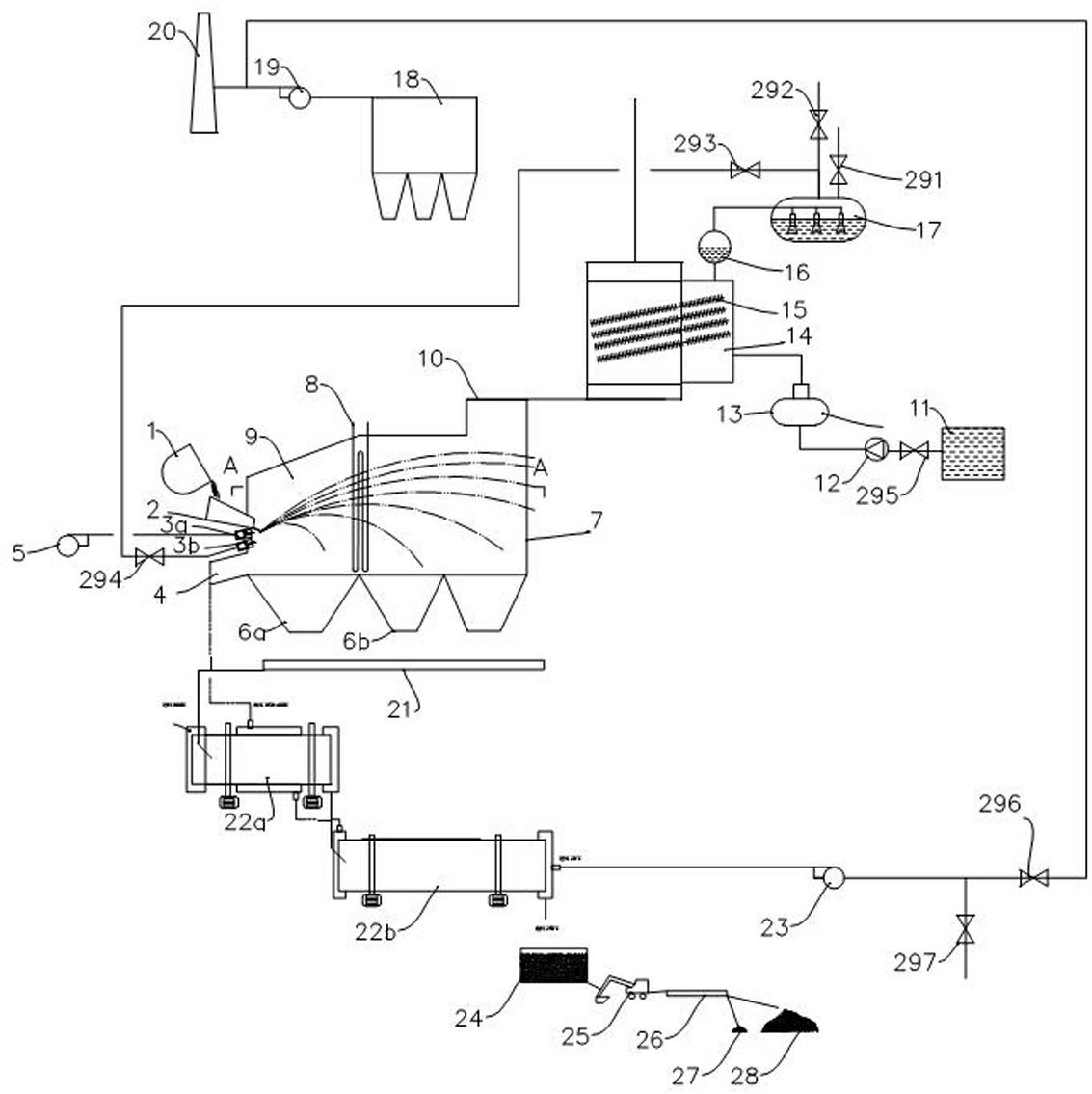
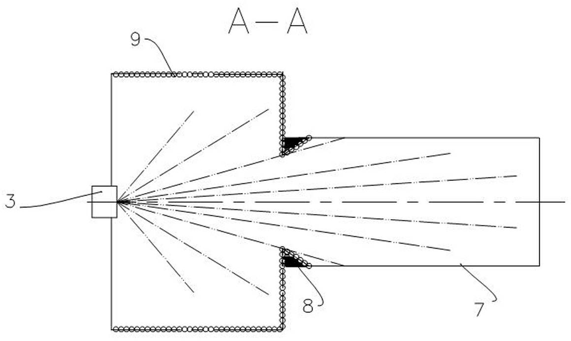
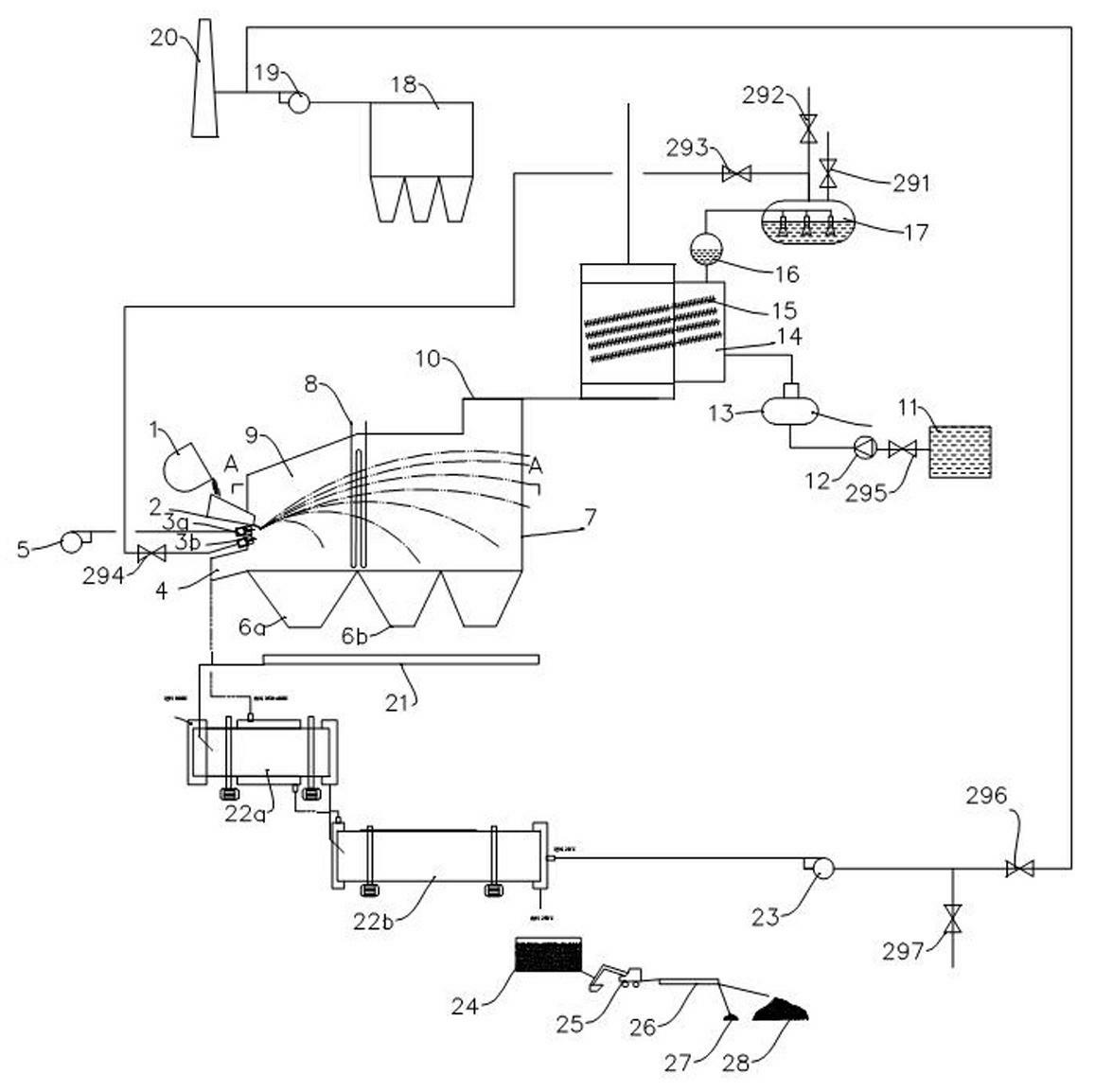
[0038] Such as figure 1 , figure 2 , the high-temperature liquid slag from the converter or electric furnace flows out from the slag bag 1 through the launder 2, and is granulated into large and small particles by the slag breaker 3. 5 receive, and the remaining smaller particles fly a long distance and then fall, and are received by the small particle ash hopper 6. The cold air used to cool the particles enters through the air inlet 4, and after exchanging the heat of the slag, it becomes hot air and is discharged from the air outlet 10, and then the waste heat is recovered.

[0039] The slag particles collected by the ash hopper 6 are transported to the buffer machine 22a and the cooling machine 22b through the ash conveyor 21 for heat exchange of the solid slag particles. The last lower temperature slag particles enter the shallow stuffy pool 24 for stabilization, then dig out through excavator 25, and magnetically select scrap iron and steel 27 through magnetic separato...


PUM


Abstract

The invention relates to a treatment device of liquid slag. The treatment device comprises a slag pot and a launder and is characterized by further comprising a granulating heat exchange bin, a nozzle, a heat exchanger, a cooling device and an ash conveyor; the slag pot is arranged on the launder; the nozzle and the launder are arranged at the entrance of the granulating heat exchange bin; the nozzle is arranged under the launder; the granulating heat exchange bin is provided with an air inlet and an air outlet; an ash bucket is arranged at the bottom of the granulating heat exchange bin. Perfect function settings enable the afterheat recovery effect of the device to be better.

Description

technical field [0001] The invention relates to a waste recovery device in the iron or steel smelting process, in particular to a liquid slag processing device. Background technique [0002] The temperature of high-temperature molten slag in the steel industry generally reaches 1600°C, and a large amount of heat is currently wasted. Moreover, the slag contains a certain proportion of scrap iron and steel, and if all of them can be recycled, the benefits will be huge. At the same time, if the added value of the waste residue can be increased, the benefits will be considerable. [0003] Whether it is from the perspective of recovering the sensible heat of molten slag or from the perspective of slag treatment, dry granulation is recognized as the most promising technology at present, including wind crushing granulation, granulation wheel granulation, and rotor granulation. and so on. [0004] However, it is not easy to granulate and solidify high-temperature molten slag in a...

Claims


Application Information

Patent Timeline
IPC IPC(8): C21B3/06
CPCY02P10/20Y02W30/50
Inventor 谈庆雷震东张鹏徐长存李晓宇
Owner 无锡市东方环境工程设计研究所
Learn More