
Hybrid Mode Fluxgate Current Transducer

A current transducer, excitation current technology, applied in voltage/current isolation, using DC to AC for measurement, instruments, etc., can solve the problem of not adapting to the accuracy of small amplitude current, and achieve the effect of low production cost

Active Publication Date: 2015-11-25
莱姆电子(中国)有限公司
View PDF7 Cites 0 Cited by
  • Summary
  • Abstract
  • Description
  • Claims
  • Application Information

AI Technical Summary

Problems solved by technology

One of the difficulties involved in battery monitoring applications is current measurement, where the measurement range (DC) can typically vary from 10mA up to 1000A
The low cost current transducers available today are not well suited to work with sufficient accuracy for small amplitude currents while supporting very large measurement ranges ranging from trickle charge (float) currents of a few milliamps to hundreds of amps of battery discharge and recharge current

Method used


Image

  • Hybrid Mode Fluxgate Current Transducer
  • Hybrid Mode Fluxgate Current Transducer
  • Hybrid Mode Fluxgate Current Transducer

Examples


Embodiment Construction

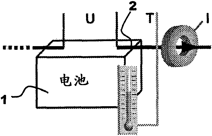
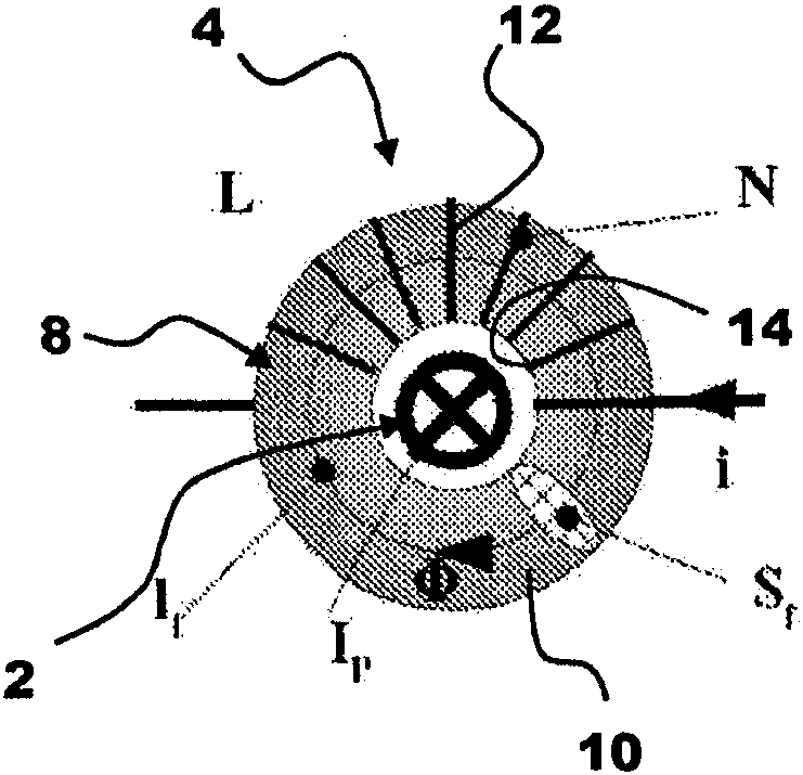
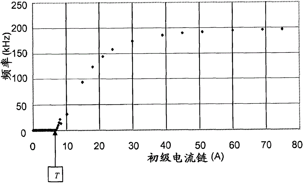
[0039] refer to figure 1 , figure 2 with Figure 7 , according to an embodiment of the current transducer of the invention, for measuring the primary current I flowing in the primary conductor 2, for example connected to a battery 1 or other electrical equipment or motor P , the primary current corresponds to the charging or discharging current of the battery, or the driving current of the motor. The transducer comprises an inductor 4 (denoted inductance L) connected to a measurement circuit 6 . The inductor includes a magnetic circuit 8 and a secondary coil (also referred to as an exciting coil) 12. The magnetic circuit 8 includes a magnetic core 10 made of high permeability material (soft magnetic material), and the secondary coil 12 surrounds the saturable magnetic core. at least partially entangled. The secondary coil 12 is connected to a measurement circuit 6 which supplies an excitation current +i, -i through the secondary coil which is configured to saturate the co...


PUM


Abstract

Electrical current transducer comprising a measuring circuit (6) and an inductor (4) for measuring a primary current / P flowing in a primary conductor (2), the inductor comprising a saturable magnetic core (10) made of a highly permeable magnetic material and a secondary coil (12) for carrying an alternating excitation i configured to alternatingly saturate the magnetic core, the coil being connected to the measuring circuit. The measuring circuit is configured to measure a mean value of the excitation current in the secondary coil and determine therefrom a value of the primary current for small current amplitudes, the measuring circuit being further configured for evaluating the frequency of the excitation current i and determining therefrom the value of the primary current for large currents.

Description

technical field [0001] The invention relates to current transducers, especially of the fluxgate type. Background technique [0002] Conventional fluxgate current transducers typically include a magnetic core of high permeability soft magnetic material that is subjected to an alternating magnetic field from a fluxgate field coil. The alternating magnetic field of the field coil saturates the core in an alternating fashion. In the presence of a magnetic field, such as an external field generated by a current flowing in the primary conductor, the saturation characteristic of the soft core becomes (obviously, seen from the secondary side) asymmetrical and produces a corresponding Signal. The resulting signal is related to the amplitude of the external magnetic field. In a closed loop current transducer, this signal is used in a feedback loop to drive a secondary coil on a magnetic circuit configured to cancel the magnetic field effect caused by the primary current coupling. ...

Claims


Application Information

Patent Timeline
Patent Type & Authority Patents(China)
IPC IPC(8): G01R19/20G01R15/18
CPCG01R19/20G01R15/185
Inventor W·泰帕小幡宽畠山自
Owner 莱姆电子(中国)有限公司
Learn More