

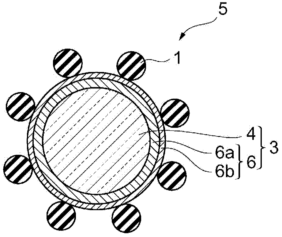
Coated conductive particles and method for producing same
A technology of conductive particles and manufacturing methods, which can be used in printed circuit manufacturing, cable/conductor manufacturing, conductive connection, etc., can solve problems such as rising connection resistance and poor connection between electrodes of opposite circuits, and achieve excellent moisture absorption resistance and coating The rate deviation is small and the effect of avoiding agglutination
- Summary
- Abstract
- Description
- Claims
- Application Information
AI Technical Summary
Problems solved by technology
Method used
Image

Examples
Embodiment 1
[0101] (1) Preparation of composite conductive particles
[0102] 100 g of resin particles (crosslinked polystyrene particles) with an average particle diameter of 3.8 μm were added to 100 mL of Atotech Neoganth 834 (Atotech Japan Co., Ltd., trade name) containing 8% by mass as a palladium catalyst. palladium catalyst solution and stirred at 30°C for 30 minutes. Then, it was filtered with a φ3 μm membrane filter (manufactured by Milipore Co., Ltd.), and washed with water. The water-washed resin particles were added to a 0.5% by mass dimethylamine borane solution adjusted to pH 6.0 to obtain surface-activated resin particles.
[0103] Next, the surface-activated resin particles were dispersed in 200 mL of 0.2% ammonia solution, and heated to 65°C. Then, the electroless plating solution (dropping solution A and dropping solution B) shown in Example 1 of Table 1 was added dropwise thereto at a dropping rate of 50 mL / min with each dropping solution to form thick coating. The ...
Embodiment 2
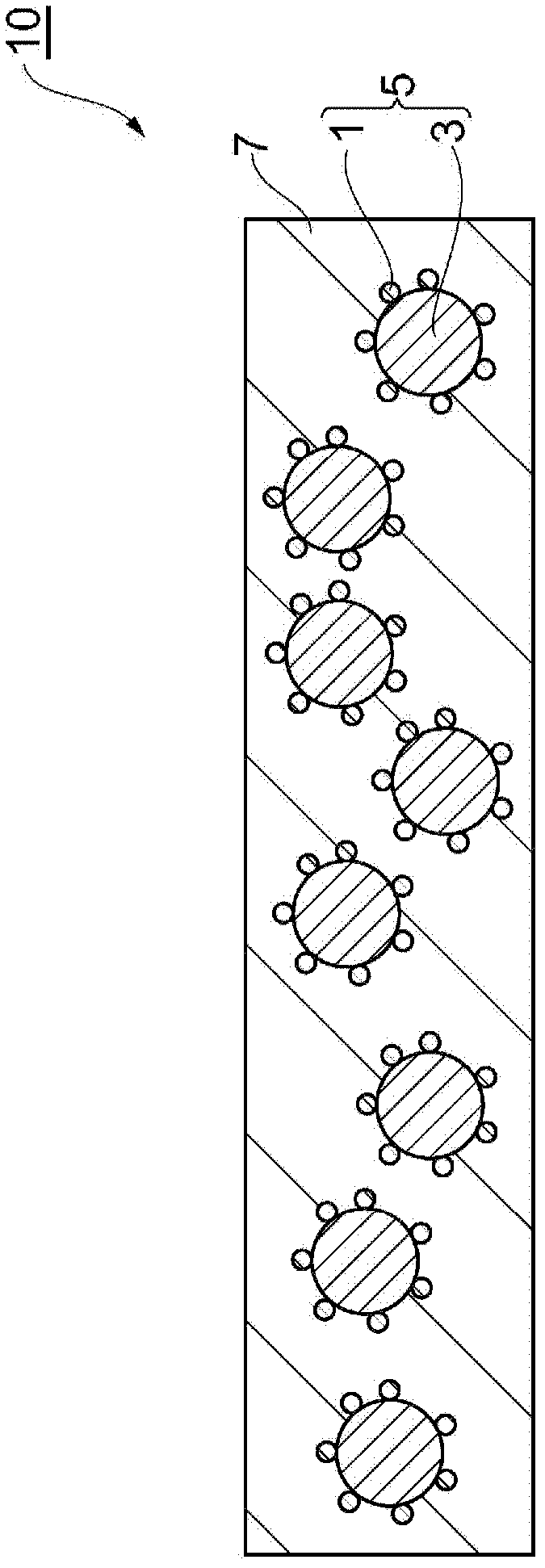
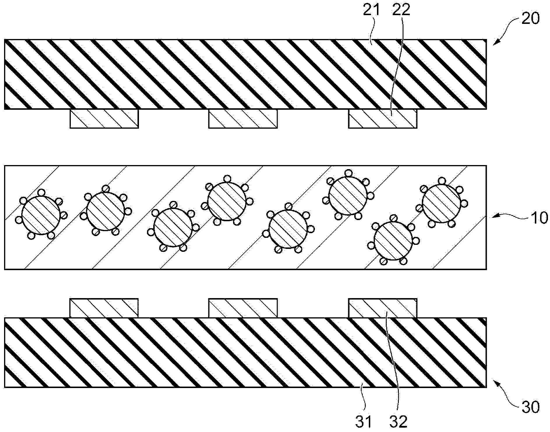
[0116] Except using the electroless plating solution shown in Example 2 of Table 1, in the same manner as in Example 1, a Composite conductive particles 2 with thickness nickel-palladium alloy coating. The appearance of the particles after plating was good. Next, according to the same procedure as in Example 1, the silica particles were attached to the composite conductive particles 2 to manufacture the coated conductive particles 2 coated with the silica particles, and an anisotropic conductive adhesive film was further formed. Fabrication and circuit connection using the adhesive film.
Embodiment 3
[0118] Except using the electroless plating solution shown in Example 3 of Table 1, in the same manner as in Example 1, a Composite conductive particles 3 thick nickel-palladium alloy plating. Although the appearance of the particles after plating was generally good, partial peeling occurred. Next, according to the same procedure as in Example 1, the silica particles were attached to the composite conductive particles 3 to manufacture the coated conductive particles 3 coated with the silica particles, and an anisotropic conductive adhesive film was further formed. Fabrication and circuit connection using the adhesive film.
PUM
| Property | Measurement | Unit |
|---|---|---|
| particle diameter | aaaaa | aaaaa |
| particle diameter | aaaaa | aaaaa |
| particle size | aaaaa | aaaaa |
Abstract
Description
Claims
Application Information