In-plane switching mode liquid crystal display

A liquid crystal display, internal switching technology, applied in the direction of instruments, optics, nonlinear optics, etc., can solve problems such as difficult to manufacture products, display color changes, low price competitiveness, etc., and achieve high yield effects

Active Publication Date: 2012-05-30
DONGWOO FINE CHEM CO LTD
View PDF5 Cites 2 Cited by
  • Summary
  • Abstract
  • Description
  • Claims
  • Application Information

AI Technical Summary

Problems solved by technology

Elliptical polarized light creates a problem: because it changes polarization in the liquid crystal cell, this causes the color of the display to change
[0009] In-plane switching mode liquid crystal displays use three compensation film-type coupled polarizing plates formed by laminating two layers with different optical properties on one side of the liquid crystal layer (one isotropic film below and two above Compensation layer), or it is difficult to have a large area Z-axis orientation film due to the lower economic efficiency and the necessary shrinking process caused by the use of shrink film in the manufacturing process
[0010] Therefore, it is difficult to manufacture thinner products due to the use of coupled polarizing plates laminated by three compensation films; bending due to changes in temperature or humidity due to the difference in thickness on both sides of the liquid crystal cell; and Less price-competitive, whose use is limited to high-cost in-plane switching-mode LCDs
In addition, since it is not easy to manufacture a wide polarizing plate including a polarizing plate and a compensation film, it is difficult to develop a large-sized liquid crystal display

Method used


Image

  • In-plane switching mode liquid crystal display
  • In-plane switching mode liquid crystal display
  • In-plane switching mode liquid crystal display

Examples


example 1

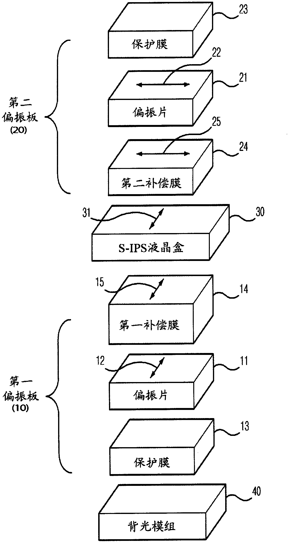
[0089] According to the actual measured data of each optical film of the present invention, liquid crystal cell and backlight module with figure 1 The stacked structure shown was applied to TECH WIZ LCD 1D (Sanayi System Co., Ltd., Korea). described in detail below figure 1 Structure.

[0090] Starting from the backlight module 40 side, the first polarizing plate 10, the in-plane switching mode liquid crystal cell 30 (when the liquid crystal orientation is measured in the counterclockwise direction from the right horizontal direction of the display side under the state where no voltage is applied), the liquid crystal cell has 90° liquid crystal orientation) and a second polarizing plate 20, wherein the first polarizing plate 10 is formed by laminating the first compensation film 14, the polarizing plate 11 and the protective film 13 from the liquid crystal cell 30 side, and the first polarizing plate 10 is formed from the liquid crystal cell 30 side The second polarizing pla...

example 2

[0110] Although the same configuration as in Example 1, the second compensation film 24 has an in-plane retardation (R0) of 200 nm and a refractive index ratio (NZ) of −0.5, and the first compensation film 14 has an in-plane retardation ( R0) and a refractive index ratio (NZ) of -1.1, the second compensation film 24 and the first compensation film 14 are used to manufacture an in-plane switching mode liquid crystal display.

[0111] Depending on the wavelength, the variation of the polarization state in a switch-mode liquid crystal display above the Poincaré sphere is related to Figure 6 Similarly, moreover, the transmittance results for all light directions are the same as Figure 8 same. able to pass Figure 8 Confirm that since the blue portion is wider at the center, a wider viewing angle is ensured.

example 3

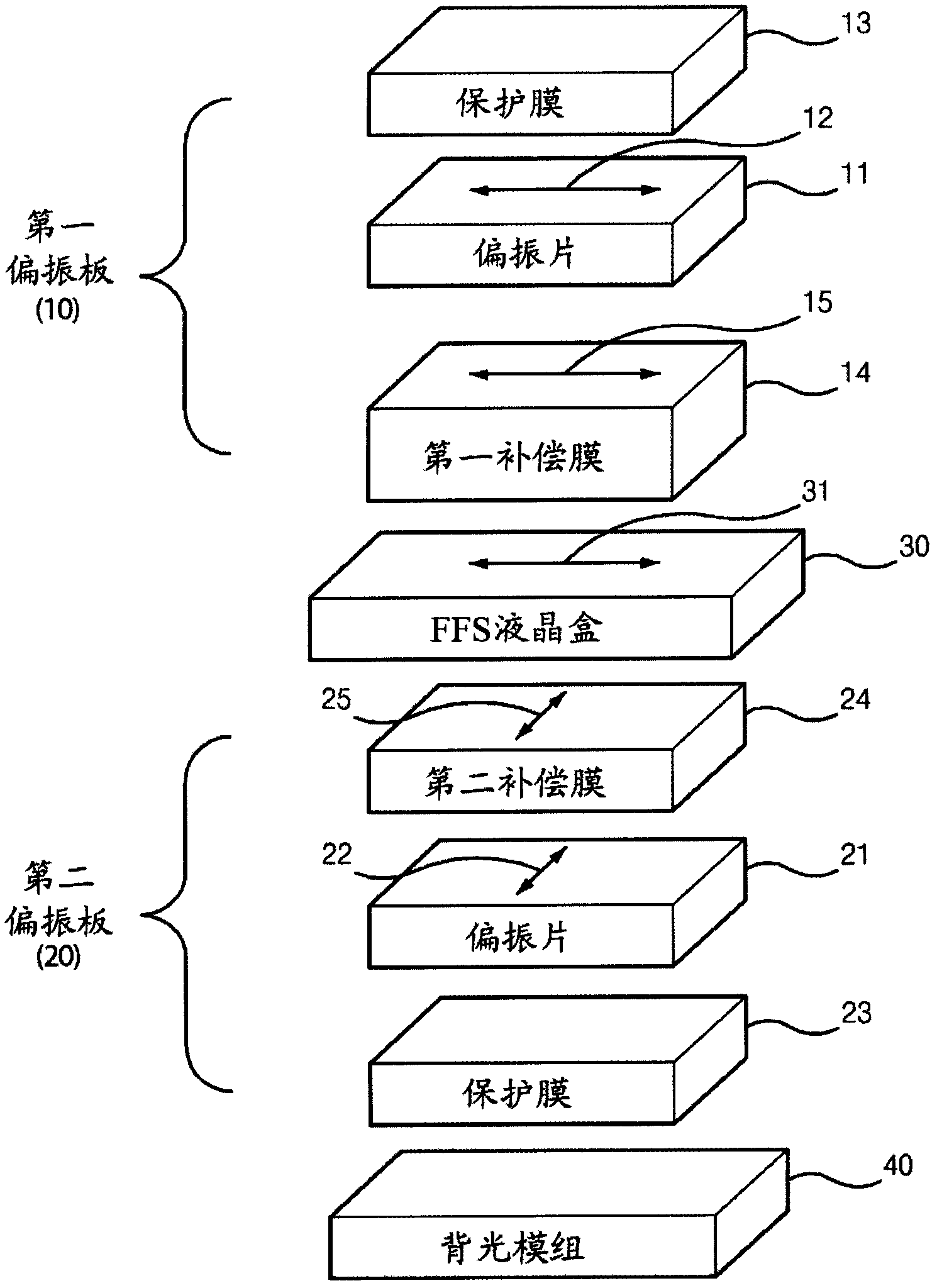
[0113] Although the configuration is the same as in example 1, in figure 2 In the stacked structure shown, the second compensation film 24 has an in-plane retardation (R0) of 270nm and a refractive index ratio (NZ) of -0.5, and the first compensation film 14 has an in-plane retardation (R0) of 60nm, -150nm The thickness direction retardation (Rth) and the refractive index ratio (NZ) of -2, and the in-plane switching mode liquid crystal display was fabricated using the second compensation film 24 and the first compensation film 14 . In this case, an in-plane switching mode liquid crystal cell 30 (FFS) whose liquid crystal orientation was 0° when measured counterclockwise from the right horizontal direction of the display in a state where no voltage was received was used.

[0114] Figure 9 showing the variation of the polarization state of an in-plane switching mode liquid crystal display on a Poincaré sphere at viewing angles of Φ=45° and θ=60° according to wavelength, and ...


PUM

PropertyMeasurementUnit
thicknessaaaaaaaaaa
degree of polarizationaaaaaaaaaa
transmittivityaaaaaaaaaa

Abstract

The present invention relates to an in-plane switching mode liquid crystal display. More precisely, the present invention relates to an in-plane switching mode liquid crystal display including a first polarizing plate, a second polarizing plate and a liquid crystal cell, designed to have wide viewing angle and to be economical, because the optical properties of the compensation film are determined by changes of the polarization state of liquid crystal alignment on a Poincare Sphere, and the contrast in the inclined visual direction is improved due to a slow axis of a compensation film of the first polarizing plate to be parallel to the liquid crystal alignment and to an absorption axis of a polarizer. The present invention can implement mass production of thin liquid crystal displays with high yield (reducing defect ratio due to foreign substances or impurities) and can provide a very large liquid crystal display with its possibility to produce larger, coupled polarizing plate since it is possible to ensure a wide viewing angle with only one sheet of compensation film for the upper polarizing plate and the lower polarizing plate.

Description

technical field [0001] The present invention relates to an in-plane switching mode liquid crystal display capable of securing a wide viewing angle by improving contrast in oblique viewing directions. Background technique [0002] Liquid crystal displays (LCDs) are widely used as general image displays. Although it has various excellent characteristics, a narrow viewing angle is pointed out as a drawback. [0003] The modes of liquid crystal displays can be classified according to the initial arrangement of liquid crystal cells, the structure of electrodes, and the properties of liquid crystals, and the most commonly used modes of liquid crystal displays are twisted nematic (TN) mode, vertical alignment (VA) mode, and in-plane switching ( IPS) mode. [0004] In addition, according to whether it transmits light when no voltage is received, it is divided into normally black mode and normally white mode. According to the area and initial arrangement of the liquid crystal, the ...

Claims


Application Information

Patent Timeline
Patent Type & Authority Applications(China)
IPC IPC(8): G02F1/1335G02B5/30
CPCG02F2413/08G02F2413/05G02F2413/02G02F1/134363G02F2001/134372G02F1/133634G02B5/3083G02F2413/12G02F1/134372G02B5/30G02F1/1335
Inventor 金奉春
Owner DONGWOO FINE CHEM CO LTD
Why Eureka
Try Eureka