
Device and method for continuously preparing high-purity single/double-wall carbon nano tubes

A double-walled carbon nanotube, high-purity technology, applied in the direction of carbon nanotubes, nanocarbon, nanotechnology, etc., can solve the problems of time-consuming purification, difficult operation, and small product output, so as to achieve easy installation and support, and avoid environmental pollution , the effect of saving the amount of acid

Active Publication Date: 2014-01-01
TSINGHUA UNIV
View PDF3 Cites 0 Cited by
  • Summary
  • Abstract
  • Description
  • Claims
  • Application Information

AI Technical Summary

Problems solved by technology

However, a large number of catalysts quickly cracks hydrocarbons and produces a large amount of hydrogen, which leads to the rapid reduction and sintering of nano-metal catalysts, which easily produces multi-walled carbon nanotubes with large diameters, resulting in a decrease in product selectivity.
In the type (2) method, the residence time of the catalyst in the reactor is too short, and when it is still active, it has already left the reactor. The activity is not fully utilized, and the catalyst becomes an impurity in the product. Purification is time-consuming, laborious and pollutes the environment.
The catalyst preparation scale of the (3) class method is small, not easy to enlarge, compared with the (1), (2) class method, the product output is too small
There is a coupled reactor technology that uses riser, down-bed and turbulent fluidized bed to solve the contradiction between product selectivity and low yield, but the device is relatively complicated and the operation is relatively difficult
Due to technical defects and bottlenecks, the absolute output of single / double-walled carbon nanotubes in the world is very low at present, and the price is expensive, generally reaching 100-1000 US dollars / gram, which seriously limits the application research of single / double-walled carbon nanotubes and commercialization

Method used


Image

  • Device and method for continuously preparing high-purity single/double-wall carbon nano tubes
  • Device and method for continuously preparing high-purity single/double-wall carbon nano tubes

Examples


Embodiment 1

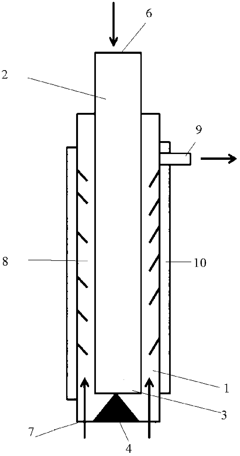
[0025] use as figure 1 In the reaction system shown, the descending bed 1 is inserted into the riser 2; the descending bed 1 has a gas-solid inlet 6 and a gas-solid outlet 3; the riser 2 has a gas inlet 7, a component area 8, and a gas-solid outlet 9. A heating system 10 and a conical structure 4; the gas-solid outlet 3 of the descending bed 1 is adjacent to the lower end of the conical structure 4 in the riser 2; the nozzle structure of the gas-solid outlet 3 is a fully open structure, and the lifting The gas inlet 7 of the pipe 2 is a plurality of symmetrical nozzles along the lower end of the riser 2 except the area occupied by the tapered structure 4, and the gas-solid outlet 9 of the riser 2 is arranged on the top of the riser 2; The ratio of the area to the cross-sectional area of ​​the riser 2 is 10:1.

[0026] Catalyst uses Fe / MgO catalyst (Fe mass percent is 2%, all the other are MgO, particle diameter is 20 microns, bulk density is 1800kg / m 3 , the specific surface...

Embodiment 2

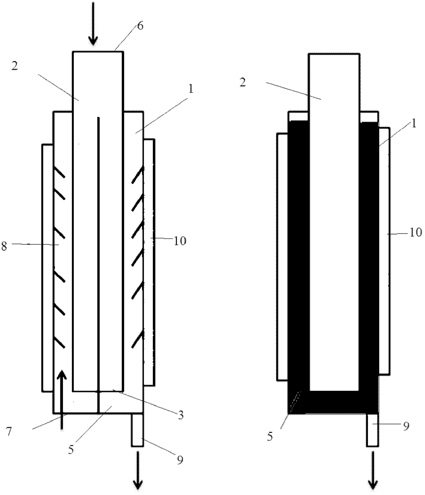
[0034] use as figure 2In the reaction system shown, the descending bed 1 is inserted into the riser 2; the descending bed 1 has a gas-solid inlet 6 and a gas-solid outlet 3; the riser 2 has a gas inlet 7, a component area 8, and a gas-solid outlet 9, a heating system 10, a partition 5; the gas-solid outlet 3 of the downer bed 1 is adjacent to the lower end of the partition 5 in the riser 2, and the partition 5 divides the riser 2 into two isolated bottom and middle parts. The two isolated areas communicate at the top of the riser 2, the bottom of one side of the partition 5 is provided with a gas inlet 7, the lower part of the downer bed 1 is an open structure on the same side, and a gas-solid outlet 3 is provided, and the other side of the partition 5 The bottom of the side is a closed structure, and a gas-solid outlet 9 is provided. The ratio of the cross-sectional area of ​​the downer bed 1 to the cross-sectional area of ​​the riser 2 is 1:1.

[0035] The catalyst uses Ni...

Embodiment 3

[0043] use as figure 1 In the reaction system shown, the descending bed 1 is inserted into the riser 2; the descending bed 1 has a gas-solid inlet 6 and a gas-solid outlet 3; the riser 2 has a gas inlet 7, a component area 8, and a gas-solid outlet 9. A heating system 10 and a conical structure 4; the gas-solid outlet 3 of the descending bed 1 is adjacent to the lower end of the conical structure 4 in the riser 2; the nozzle structure of the gas-solid outlet 3 is a fully open structure, and the lifting The gas inlet 7 of the pipe 2 is a plurality of symmetrical nozzles along the lower end of the riser 2 except the area occupied by the tapered structure 4, and the gas-solid outlet 9 of the riser 2 is arranged on the top of the riser 2; The ratio of the area to the cross-sectional area of ​​the riser 2 is 4:1.

[0044] Catalyst using Fe / Mo / Al 2 o 3 Catalyst (the mass proportion of Fe is 1%, the mass proportion of Mo is 1%, and the rest are Al 2 o 3 , the particle size is 2 ...


PUM

PropertyMeasurementUnit
specific surface areaaaaaaaaaaa
particle sizeaaaaaaaaaa
densityaaaaaaaaaa

Abstract

The invention discloses a device and a method for continuously preparing high-purity single / double-wall carbon nano tubes, and belongs to the technical field of preparation of carbon nano tubes. A downer of the device is sleeved into a lifting pipe, and the gas-solid outlet of the downer is adjacent to the lower end of a conical structure or a partition board in the lifting pipe. The method for preparing the single / double-wall carbon nano tubes comprises the following steps of: feeding a process gas and a catalyst from the top of the downer to finish cracking of a carbon source and the nucleation and growth process of the single / double-wall carbon nano tubes, discharging the gas and the solid from the bottom of the downer to enter the lifting pipe and flow upwards, introducing the carbon source from the bottom of the lifting pipe to ensure that the ratio of the carbon source to the hydrogen at the position is as same as that at the inlet of the downer, and further growing the single / double-wall carbon nano tubes with high selectivity. The method has the characteristics of high product purity, high yield, low preparation cost and easily amplified processes.

Description

technical field [0001] The invention belongs to the technical field of carbon nanotube preparation, and in particular relates to a device and method for continuously preparing high-purity single / double-wall carbon nanotubes. Background technique [0002] Most single / double-walled carbon nanotubes have a diameter between 0.6-2nm and a length of hundreds of microns or even tens of centimeters. They have good electrical conductivity, thermal conductivity, mechanical properties and huge specific surface area, and can be widely used in polymers. Enhancement, conductive material, field emission material, absorbing or shielding material, catalyst carrier or used in nano-circuits, etc. There are three methods for preparing single / double-walled carbon nanotubes: graphite arc, laser ablation, and chemical vapor deposition. The first two methods have expensive equipment, are not easy to scale up, and the local temperature is too high, which is easy to generate carbon impurities such a...

Claims


Application Information

Patent Timeline
Patent Type & Authority Patents(China)
IPC IPC(8): C01B31/02B82Y40/00C01B32/159C01B32/162C01B32/164
Inventor 骞伟中崔超婕郑超张强魏飞
Owner TSINGHUA UNIV
Learn More